ProductOverview
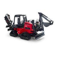
Figure7
1.Nosepanel5.Fuelreservoir
2.Leftsidepanel
6.Fuelcap
3.Grabhandles7.Steps
4.ROPSenclosure
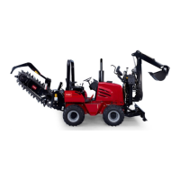
Figure8
1.Grabhandles4.Steps
2.Rightsidepanel
5.Hydraulic-uidsightgauge
3.Nosepanel6.Hydraulic-tankcap
Controls
Becomefamiliarwithallthecontrols(Figure9throughFigure
16)beforeyoustarttheengineandoperatethemachine.
CommandCenter
HomeScreenControls
Usethebuttonsonthecommandcentertocontrolthe
operationofmachinefunctions,andtonavigatetothe
machinesetupanddiagnosticscreens(Figure9).
Figure9
Homescreenshown
1.Button1(lightOn/Off
button—usedwiththelight
kitoption)
8.Button8(decreasethe
enginespeed)
2.Button2(increasethe
setpointfortheload
control—usedwiththe
load-controlkit)
9.Escape(usedtoreturnto
thehomescreen)
3.Button3(decreasethe
setpointfortheload
control—usedwiththe
load-controlkit)
10.Previousscreen(usedto
movetoapreviousscreen
functionwithinascreen
mode)
4.Button4(loadcontrol
On/Off—usedwiththe
load-controloption)
11.OK(usedtomakea
selection)
5.Button5(control
select—usetodetermine
whichattachmentthe
backll-blade/vibratory-plow
joystickoperates)
12.Nextscreen(usedtomove
tothenextscreenfunction
withinascreenmode)
6.Button6
(advanced-steering
mode—usedwiththe
advanced-steeringkit)
13.Downscreen(usedto
movedowntotheprevious
screenmodeandenter
diagnosticandcalibration
screens)
7.Button7(increasethe
enginespeed)
14.Upscreen(usedtomove
upthenextscreenmode)
15