decal100-5622nc
Figure23
3.Pushthecastorspindlethroughthecastorarm.
Installtheshims(asoriginallyinstalled)andthe
remainingspacersontothespindleshaft.Install
thetensioningcaptosecuretheassembly.
4.Removethehairpincotterandclevispinsfrom
thecastorpivotarms(Figure24).
5.Rotatetensionrodtoraiseorlowerpivotarm
untilholesarealignedwithselectedheight-of-cut
bracketholesinthecuttingunitframe(Figure
24andFigure25).
6.Inserttheclevispinsandinstallthehairpin
cotters.
7.Rotatetensionrodcounterclockwise(nger
tight)toputtensiononadjustment.
g004676
Figure24
1.Castorpivotarm3.Clevispinandhairpin
cotter
2.Axlemountingholes4.Tensionrod
decal100-5623nc
Figure25
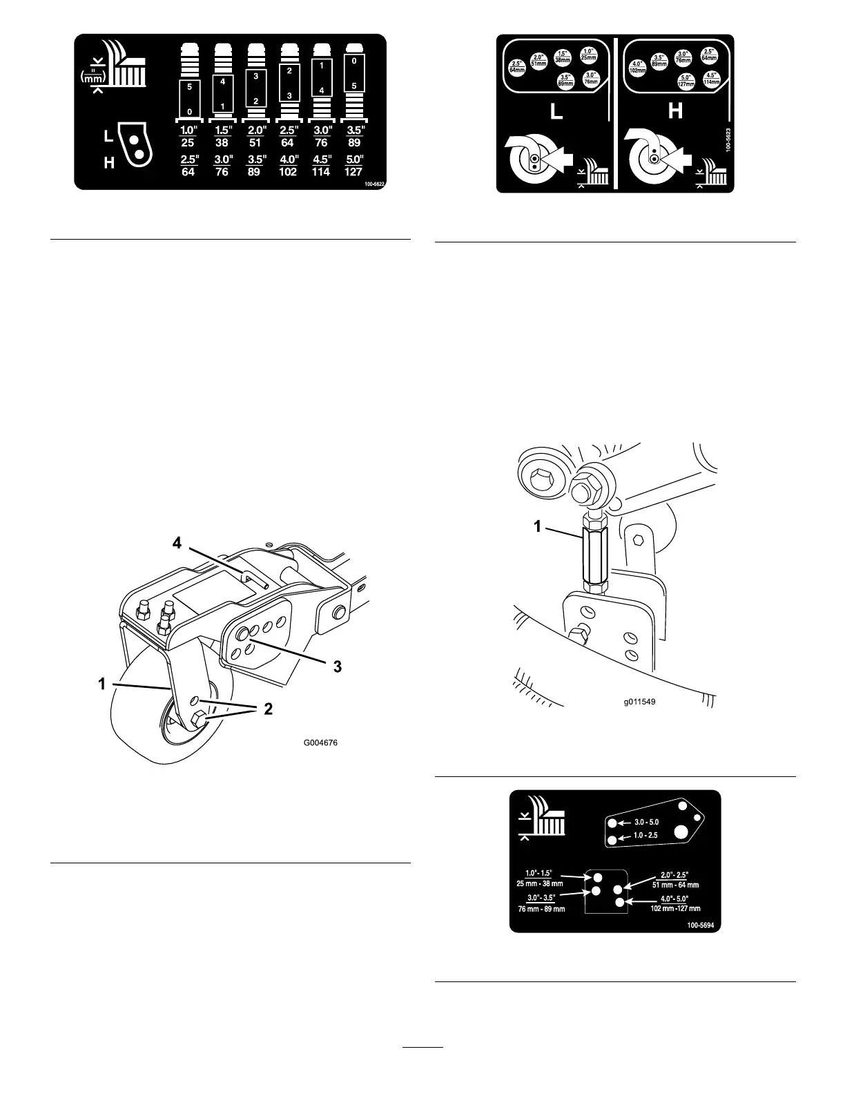
8.Removethehairpincottersandclevispins
securingthedamperlinkstothecuttingunit
brackets(Figure26).Alignthedamperlink
holeswiththeselectedheight-of-cutbracket
holesinthecuttingunitframe(Figure27),insert
theclevispins,andinstallthehairpincotters.
Important:Thedamperlinklengthshould
neverbeadjusted.Thelengthbetween
theholecentersshouldbe13.7cm(5-3/8
inches).
g011549
Figure26
1.Damperlink
decal100-5694nc
Figure27
31