AdjustingtheCounterbalance
Pressure
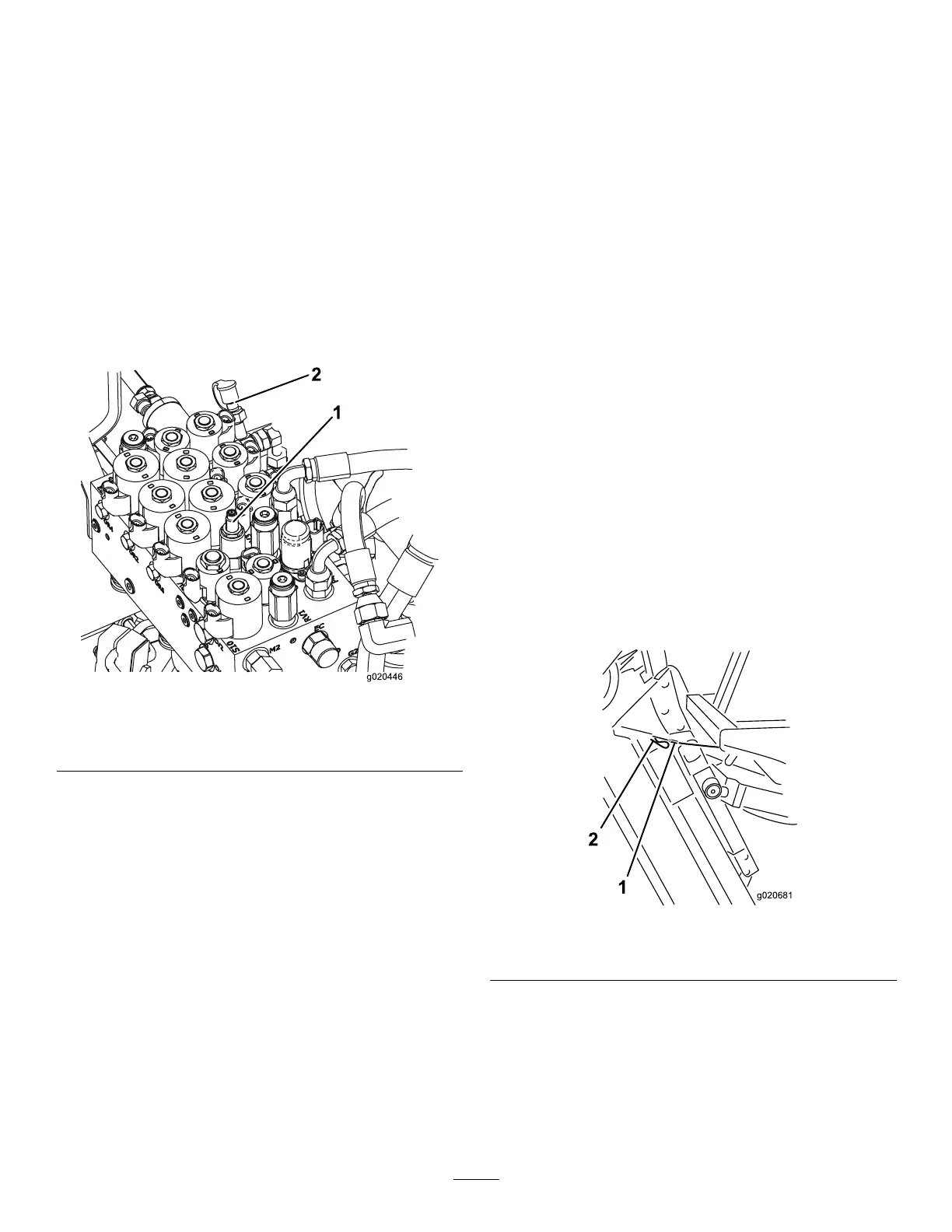
Thecounterbalancetestportisusedtotestthe
pressureinthecounterbalancecircuit(Figure81).
Therecommendedcounterbalancepressureis
2241kPa(325psi).T oadjustthecounterbalance
pressure,loosenthelocknut,rotatetheadjusting
screw(Figure81)clockwisetoincreasethepressure
orcounterclockwisetodecreasethepressure,and
tightenthelocknut.Theenginemustberunningand
thedeckloweredandintheoatpositiontocheck
thepressure.
Note:Thecasterwheelsofall3cuttingunits
shouldremainonthegroundwhenadjustingthe
counterbalanceandwithcounterbalanceapplied.
g020446
Figure81
1.Counterbalance-adjusting
screw
2.Counterbalance-testport
CuttingUnitMaintenance
Pivoting(Tilting)theFront
CuttingUnittotheUpright
Position
Note:Althoughnotneededfornormalmaintenance
procedures,youcanpivot(tilt)thefrontcuttingunitto
anuprightposition.
1.Raisethefrontcuttingunitslightlyofftheoor,
engagetheparkingbrake,shutofftheengine,
andremovethekey.
2.Removethehairpincotterandclevispin
securingthedeck-transportlatchtothelatch
plateandpivotthelatchtowardtherearofthe
deck.
3.Removethehairpincotterandclevispin
securingtheheight-of-cutchainstotherearof
thecuttingunit.
4.Starttheengine,slowlyraisethefrontcutting
unit,shutofftheengine,andremovethekey.
5.Graspthefrontofthecuttingunitandliftitto
anuprightposition.
6.Holdthecuttingunitupright,tthecableend
overthepinonthecuttingunitliftarm,and
secureitwiththehairpincotter(Figure82).
g020681
Figure82
1.Cable
2.Pin
65