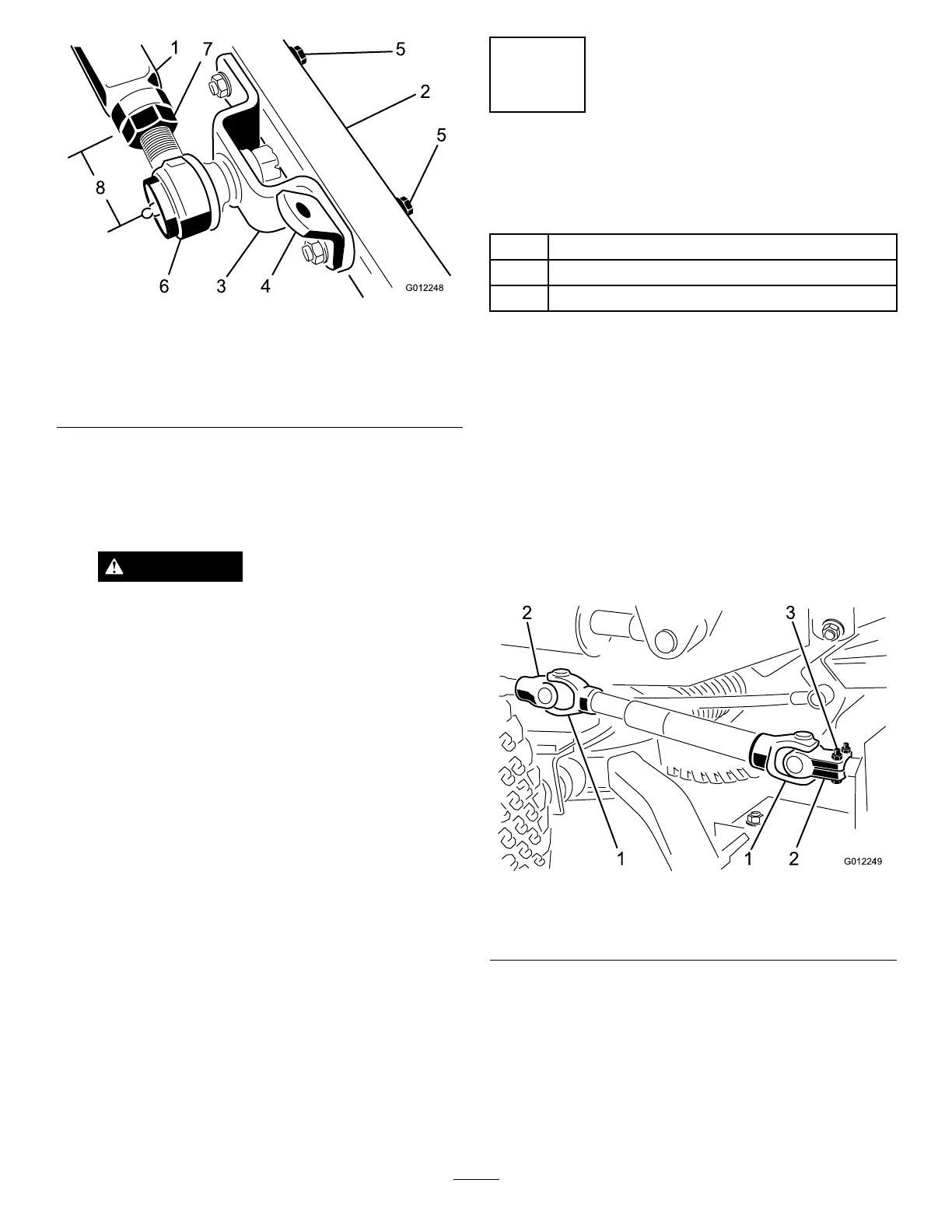
Figure7
1.Left-handpusharm5.Capscrewsandwashers
2.Castorarm
6.Balljoint
3.Balljointmount7.Jamnut
4.Chainmount
4.Haveanotherpersoncarefullypushdownonthepush
armuntiltheholesintheballjointmountlineupwith
theholesinthecastorarm.Immediatelyslidea4x4
inchblockofwoodbetweenthetopofthepusharm
andtheundersideofthechassis.
WARNING
Suddenreleaseofthepusharmcouldcause
injury.
Makesurethatthewoodenblockdoesnot
slipout.
5.Securetheballjointmountandchainbrackettothe
castorarmwiththecapscrews,atwashers,andange
nutspreviouslyremoved.Positiontheatwashersto
theoutsideofthecastorarm.Mountthechainbracket
intheforwardsetofholes.
6.Tightenthelargejamnutsecuringtheballjointtothe
pusharm.Whentighteningthejamnut,holdtheball
jointstraighttopermitproperoscillationduringraising
andloweringofthecuttingunit.Carefullyremovethe
woodblockholdingthepusharmdown.
5
ConnectingtheDriveShaftto
theCuttingUnitGearBox
Partsneededforthisprocedure:
2
Bolt,5/16x1-3/4inches
2
Locknut,5/16inches
2
Rollpin,3/16x1-1/2inches
Procedure
Important:Thedriveshaftyokesmustbeexactlyin
linewitheachotherwhentheouteryokeisinstalledon
thegearboxsplinedPTOshaft.Removethesleeveand
changetheyokepositionifthealignmentisnotcorrect.
Misalignmentofthetwoyokeswillshortenthelifeof
thedriveshaftandcauseunnecessaryvibrationwhen
thecuttingunitisoperated.
1.Lineuptheholesintheyokeandinputshaftofthe
gearbox.Slidetheyokeontotheshaftandsecurethem
togetherwitharollpinand2capscrews(5/16x1-3/4
inches)andlocknuts(5/16inch)(Figure8).
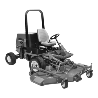
Figure8
1.Driveshaftyokes
3.Rollpinandcapscrews
2.Yokesinphase
2.MountthePTOshieldtothetopofthecuttingunit
gearboxmountingplatewiththe2self-tappingscrews
previouslyremoved.
11