intheAdjustingtheHeightofcutsection.Slidea
thrustwasherontothespindle.Pushthelargecastor
spindlethroughthefrontcastorarmandthesmall
castorspindlethroughtherearcastorarm.Install
anotherthrustwasherandtheremainingspacersonto
thespindleandinstallthetensioningcaptosecurethe
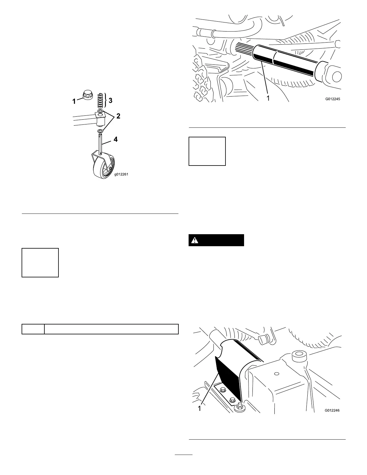
assembly(Figure2&Figure3).
Important:Thethrustwashers,notthespacers,
mustcontactthetopandbottomofthecastorarm.
Figure3
1.Tensioningcap
3.Spacers
2.Thrustwashers
4.Small(rear)castorspindle
3.Ensurethatallfourcastorwheelsaresetatthesame
height-of-cut;thenrollthecuttingunitoffofthe
woodenpallet.
2
InstallingtheDriveShafttothe
TractionUnit
Partsneededforthisprocedure:
1
Driveshaft
Procedure
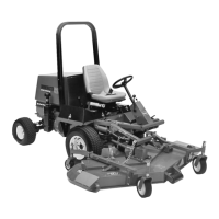
Slidethesmalleryokeendofthedriveshaftontothetraction
unitPTOshaftwhilealigningthemountingholes(Figure
4).Securethemwitharollpin.Donotinstallthefrontend
ofthedriveshaftatthistime.
Figure4
1.Driveshaft
3
ConnectingtheRight-Hand
PushArmtotheCuttingUnit
NoPartsRequired
Procedure
WARNING
Theright-handpusharmisspringloadedtoabout
45kg(100lb.).Suddenreleaseofthepusharm
couldcauseinjury.
Anotherpersonisneededtopushthearmdown
duringthisprocedure.
1.Removethe2self-tappingscrewssecuringthePTO
shieldtothetopofthecuttingunitgearboxmounting
plateandremovetheshield(Figure5).
Figure5
1.PTOshield
9