RemovingtheSteeringCylinder(continued)
CAUTION
Beforeopeningthehydraulicsystem,operateallthehydraulic
controlstoreleasesystempressureandavoidinjuryfromthe
pressurizedhydraulicuid;refertoReleasingPressurefromthe
HydraulicSystem(page5–5).
3.Forassemblypurposes,labelallthehydraulichosesandtubesthatare
connectedtothettingsonthesteeringcylinder.
4.Cleanthehydraulichoseendsbeforeyoudisconnectthehosesfromthe
steeringcylinder.
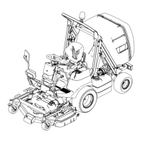
g293899
Figure91
1.Ttting8.Heightofcutvalve
2.Hose9.Fitting
3.Fitting
10.Hose
4.Hose11.Hose
5.Hose
12.Steeringcylinder
6.Hydrauliccontrolvalve
13.O-ring
7.Auxiliarycontrolvalve14.Fitting
5.Disconnectthehydraulichosesfromthesteeringcylinder.
6.Installcapsorplugsonthedisconnectedhosesandttingstoprevent
contamination.
7.Removethenuts(item16inFigure90)andwashers(10)thatsecuresthe
steeringcylindertierodend(11)tothespindle(14and15).
8.Removethe4bolts(9),washers(10)andnuts(20)thatsecuresthesteering
cylinder(13)totherearaxle(6).
9.Removethesteeringcylinder(13)fromthemachine.
10.Ifnecessary,removethetierodend(11)fromthesteeringcylinder(13).
11.Ifthehydraulicttingsaretoberemovedfromthesteeringcylinder,mark
thettingorientationforassemblypurposes.Removethettingsfromthe
steeringcylinderanddiscardtheO-ringsfromthettings.
HydraulicSystem:ServiceandRepairs
Page5–116
ProLineH800
19241SLRevB
 Loading...