RemovingandInstallingtheSlopeSensorModule(continued)
6.Wheninstallingtheslopesensormodule,tightenthefastenersthatsecure
thesensormoduletotheplateto4N·m(37in-lb).
7.Connectthewireharnessandcalibratetheslopesensor;refertoCalibrating
theSlopeSensor(page6–44).
TestingtheSlopeSensorLED
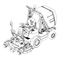
g279250
Figure140
1.LED(LightEmittingDiode)
4.Hexnut
2.Gasket5.Redwire(+)
3.Lockwasher
6.Blackwire(-)
TheslopesensorLEDislocatedonthedashboardnearthesteeringwheel.
ElectricalcurrentfortheLEDisprovidedasanoutputfromtheslopesensor
module.WhenthekeyswitchissettotheSTARTposition,theLEDlightshould
illuminatefor5secondstoindicatethatthesensorisfunctioningproperly.During
machineoperation,thelightandtheaudiblealarmindicatestheseverityofthe
slope:
•Nolight–normaloperatingconditions.
•Slow,ashinglight–moderateslop(approximately11to14°).
•Fast,ashinglightandaudiblealarm–steepslope(approximately15°or
more);proceedtoamoreshallowslope.
1.EnsurethatthekeyswitchisOFFandkeyisremovedfromtheswitch.
2.RemovethelowerfrontsteeringtowercoveranddisconnecttheLED
connectorfromthewireharness.
Note:TheTED(LightEmittingDiode)andispolaritysensitive.
3.Connecta12VDCpowersource(machinebattery)totheLEDterminals.
TheLEDshouldonlyilluminatewhenthepositive(+)leadofthepower
supplyisconnectedtothepositive(+)redwire,andthenegative(-)leadof
thepowersupplyisconnectedtothenegative(-)blackwire.
4.ReplacetheLEDifnecessary.TightentheLEDhexnutfrom18to22N·m
(162to198in-lb).
5.IftheLEDtestscorrectlyandacircuitproblemstillexists,checkthewire
harness;refertoAppendixA(pageA–1).
6.Connectthewireharness,installthesteeringtowercoverandtesttheLED
beforereturningthemachinetoservice.
ElectricalSystem:TestingtheElectricalComponents
Page6–46
ProLineH800
19241SLRevB
 Loading...