33
Adjusting the Caster Pivot
Bearing
Check after every 500 operating hours or at storage, which
ever comes first.
1. Stop the engine, set the parking brake, remove the key
and disconnect the spark plug wire(s) from the spark
plug(s).
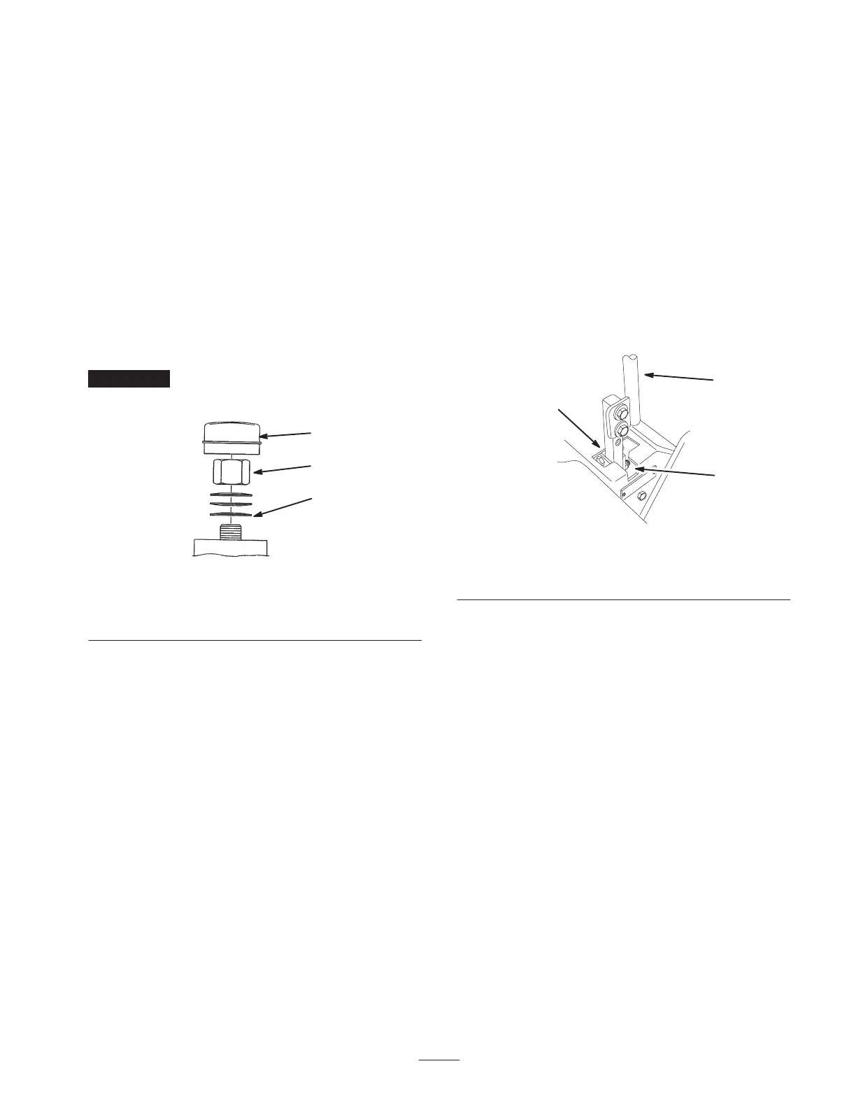
2. Remove dust cap from caster and tighten lock nut
(Fig. 42).
3. Tighten until spring washers are flat and then back off
a 1/4 turn to properly set the pre–load on the bearings
(Fig. 42).
4. Grease caster pivot. Refer to Greasing and Lubrication
on page 31.
Important Make sure spring washers are installed
correctly as shown in figure 42.
1
M–4640
2
3
Figure 42
1. Spring washers
2. Lock nut
3. Dust cap
Adjusting the Handle Neutral
If motion control levers do not align, or move easily into
the console notch, adjustment is required. Adjust each
lever, spring and rod separately.
Note: Motion control levers must be installed correctly.
See Installing the Motion Control Levers in the set–up
instructions.
1. Stop the engine, remove ignition key and tilt seat
forward.
2. Begin with either the left or right motion control lever.
3. Move lever to the neutral position but not locked
(Fig. 43).
4. Pull lever back until the clevis pin (on arm below pivot
shaft) contacts the end of the slot (just beginning to put
pressure on the spring) (Fig. 44).
5. Check where the control lever is relative to notch in
console (Fig. 43). It should be centered allowing lever
to pivot outward to the neutral lock position.
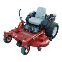
2
m–6282
1
3
Figure 43
1. Neutral locked position
2. Control lever
3. Neutral position
6. If adjustment is needed, loosen the nut and jam nut
against the yoke (Fig. 44).
7. Apply slight rearward pressure on the motion control
lever, turn the head of the adjustment bolt in the
appropriate direction until the control lever is centered
in neutral lock position (Fig. 43).
Note: Keeping rearward pressure on the lever will keep
the pin at the end of the slot and allow the adjustment bolt
to move the lever to the appropriate position.
8. Tighten the nut and jam nut (Fig. 44).