36
3
1
2
4
m–6280
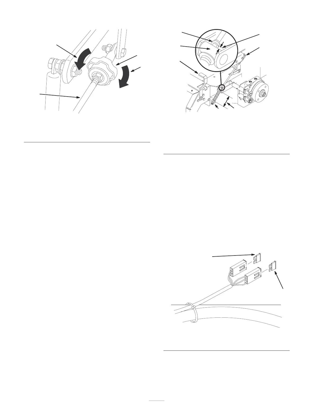
Figure 46
1. Pump rod
2. Turn this way to track left
3. Tracking knob
4. Turn this way to track right
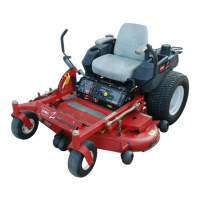
Adjusting the Parking Brake
Check parking brake for proper adjustment.
1. Disengage brake lever (lever down).
2. Measure the length of the spring. Measurement should
be 2-3/4 inch (70 mm) between washers (Fig. 47).
3. If adjustment is necessary, loosen the jam nut below
the spring and tighten the nut directly below the yoke
(Fig. 47). Turn the nut until the correct measurement is
obtained. Tighten the two nuts together and repeat on
opposite side of unit.
4. Turn nuts clockwise to shorten spring length and turn
counterclockwise to lengthen the spring.
5. Engage parking brake, lever up.
6. Measure the distance between the trunnion roller and
the collar on brake rod. Measurement should be
3/16 –1/4 inch (5–7 mm) (Fig. 47).
7. If adjustment is necessary, loosen the jam nut directly
below the yoke. Turn the bottom adjusting nuts until
the correct measurement is obtained (Fig. 47). Tighten
jam nut at yoke
M–4120
11
2
3
4
7
5
6
Figure 47
1. Brake lever
2. Spring 2–3/4 inch (70 mm)
3. Adjusting nuts
4. Collar on brake rod
5. 3/16 –1/4 inch (5–7 mm)
6. Jam nut and yoke
7. Trunion
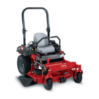
Servicing the Fuse
Service Interval/Specification
The electrical system is protected by fuses. It requires no
maintenance: however, if a fuse blows check
component/circuit for malfunction or short.
Fuse: Main F1—20 amp, blade-type
Alternator F2—20 amp, blade-type
1. Raise the seat to gain access to fuse holder (Fig. 48).
2. To replace fuses pull out on the fuse to remove it
(Fig. 48).
m–3653
2
1
Figure 48
1. Main—20 amp 2. Alternator—20 amp