41
m–1256
1
2
3
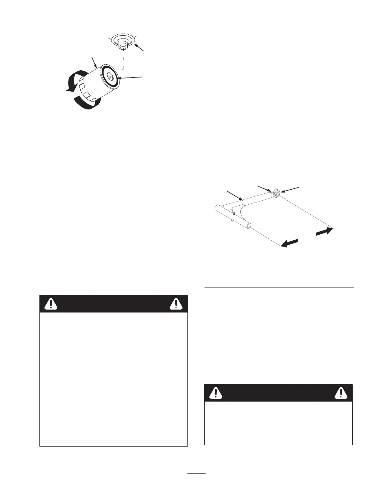
Figure 54
1. Hydraulic filter
2. Gasket
3. Adapter
Bleeding the Hydraulic System
The traction system is self bleeding, however, it may be
necessary to bleed the system if fluid is changed or after
work is performed on the system.
1. Raise rear of the machine so wheels are off the ground
and support with jack stands.
2. Start the engine and run at low idle speed. Engage the
lever and traction on one side and spin the wheel by
hand.
3. When the wheel begins to spin on its own, keep it
engaged until wheel drives smoothly. (minimum
2 minutes)
4. Check hydraulic fluid level and add as required to
maintain proper level.
5. Repeat this procedure on the opposite wheel.
Hydraulic fluid escaping under pressure can
penetrate skin and cause injury.
• If hydraulic fluid is injected into the skin it
must be surgically removed within a few hours
by a doctor familiar with this type of injury.
Gangrene may result if this is not done.
• Keep body and hands away from pin hole leaks
or nozzles that eject high pressure hydraulic
fluid.
• Use cardboard or paper to find hydraulic leaks.
• Safely relieve all pressure in the hydraulic
system before performing any work on the
hydraulic system.
• Make sure all hydraulic fluid hoses and lines
are in good condition and all hydraulic
connections and fittings are tight before
applying pressure to hydraulic system.
Warning
Checking the Hydraulic Lines
After every 100 operating hours, check hydraulic lines and
hoses for leaks, loose fittings, kinked lines, loose
mounting supports, wear, weather and chemical
deterioration. Make necessary repairs before operating.
Note: Keep areas around hydraulic system clean from
grass and debris build up.
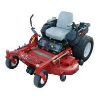
Adjusting the Push Arms
1. To adjust push arms, loosen jam nut and rotate ball
joint counterclockwise, one turn at a time. (Fig. 55).
2. Adjust each side the same amount. Each push arm
should have a nominal length of 15-5/16 inch
(389mm) (Fig. 55).
Note: Increase tension by lengthening the push arms and
decrease tension by shortening push arms.
4
3
2
1
m–6273
Figure 55
1. Push arm
2. 15-5/16 inch (389 mm)
nominal
3. Jam nut
4. Ball joint
Cleaning Under the Deck
Remove grass build up under deck daily.
1. Position mower on a flat surface. Stop the engine, set
the parking brake, remove the key and disconnect the
spark plug wire(s) from the spark plug(s).
2. Raise deck to the transport position.
3. Lift the front of unit and support unit using jack
stands.
Danger
Mechanical or hydraulic jacks may fail to support
machine and cause a serious injury.
• Use jack stand when supporting machine.
• Do not use hydraulic jacks.