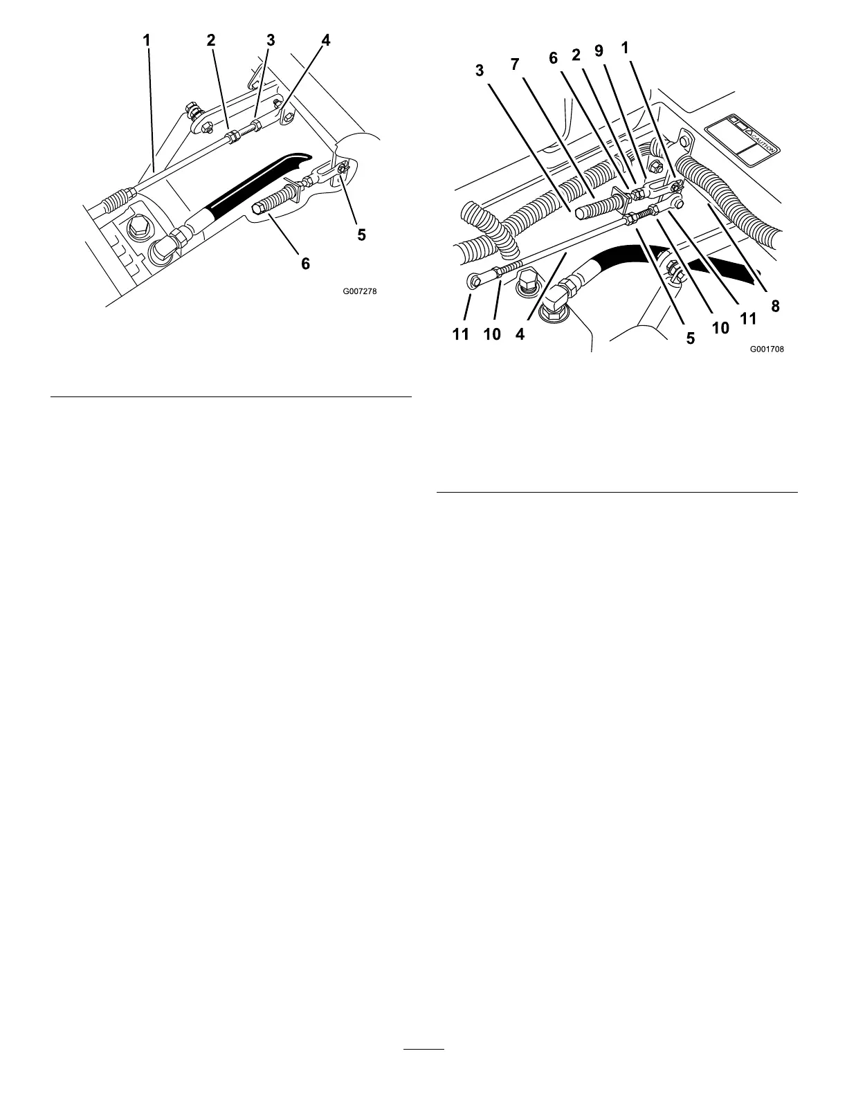
Figure56
1.Pumprod4.Balljoint
2.Doublenuts5.Yoke
3.Locknut6.Adjustmentbolt
4.Movethemotioncontrolleverforwardandreverse,
thenbacktoneutral.Thewheelmuststopturning
orslightlycreepinreverse.
5.Openthethrottletofast.Makesurethewheel
remainsstoppedorslightlycreepsinreverse,adjust
ifnecessary.
6.Tightenthelocknutattheballjoint(Figure56).
SettingtheLeft-handHydraulicPump
NeutralPosition
1.Loosenthelocknutsattheballjointsonthepump
controlrod(Figure57).
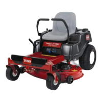
Figure57
1.Clevispininslot7.Spring
2.Nutagainstyoke
8.Pivotshaft
3.Adjustmentbolt9.Yoke
4.Pumprod10.Locknut
5.Doublenuts11.Balljoint
6.Jamnut
2.Starttheengine,openthrottle1/2way,andrelease
parkingbrake.RefertoStartingandStoppingthe
EngineinOperation,page12.
Note:Themotioncontrollevermustbeinneutral
whilemakinganyadjustments.
Note:Thefrontnutonthepumprodhasleft-hand
threads.
3.Adjustthepumprodlengthbyrotatingthedouble
nutsonrod,intheappropriatedirection,untilwheel
isstillorslightlycreepsinreverse(Figure57).
4.Movethemotioncontrolleverforwardandreverse,
thenbacktoneutral.Thewheelmuststopturning
orslightlycreepinreverse.
5.Openthethrottletofast.Makesurethewheel
remainsstoppedorslightlycreepsinreverse,adjust
ifnecessary.
6.Tightenthelocknutsattheballjoints(Figure57).
42