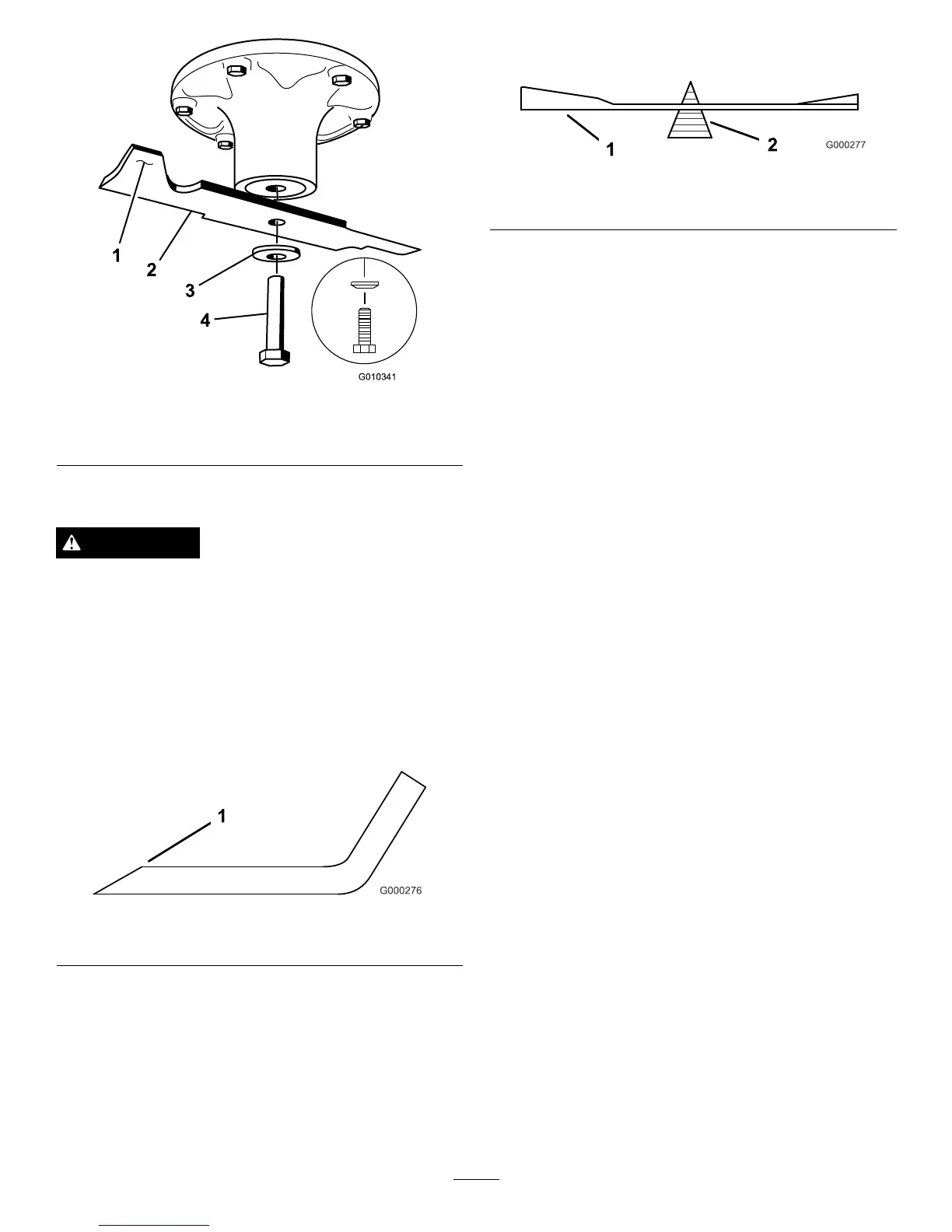
Figure55
1.SailAreaofBlade3.Curvedwasher
2.Blade4.BladeBolt
SharpeningtheBlades
WARNING
Whensharpeningblade,piecesofbladecouldbe
thrownandcauseseriousinjury.
Wearpropereyeprotectionwhensharpeningblade.
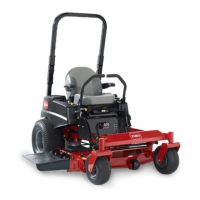
1.Usealetosharpenthecuttingedgeatbothendsof
theblade(Figure56).
Note:Maintaintheoriginalangle.
Note:Thebladeretainsitsbalanceifthesameamount
ofmaterialisremovedfrombothcuttingedges.
Figure56
1.Sharpenatoriginalangle
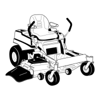
2.Checkthebalanceofthebladebyputtingitonablade
balancer(Figure57).
•Ifthebladestaysinahorizontalposition,theblade
isbalancedandcanbeused.
•Ifthebladeisnotbalanced,performthefollowing
steps:
A.Filesomemetalofftheendofthesailarea
only(
Figure55).
B.Repeatthisprocedureuntilthebladeis
balanced.
Figure57
1.Blade2.Balancer
InstallingtheBlades
1.Installthebladeontothespindleshaft(Figure55).
Important:Thecurvedpartoftheblademust
pointupwardtowardtheinsideofthemowerto
ensurepropercutting.
2.Installthespringdiskandbladebolt(Figure55).
Note:Thespringdiskconemustbeinstalledtoward
thebolthead
3.Threadtheboltintotheshaftclockwiseandtorquethe
boltto135-150N-m(100-110ft-lb).
MowerDeckLeveling
Checktoensurethemowerdeckislevelanytimeyouinstall
themowerorwhenyouseeanunevencutonyourlawn.
Themowerdeckmustbecheckedforbentbladespriorto
leveling;anybentbladesmustberemovedandreplaced;refer
to
CheckingforBentBlades(page39)beforecontinuing.
Themowerdeckmustbeleveledside-to-siderstthenthe
fronttorearslopecanbeadjusted.
Requirements:
•Themachinemustbeonalevelsurface.
•Allfourtiresmustbeproperlyinated;referto
Checking
theTirePressure(page36).
CheckingSide-to-SideLevel
Themowerbladesmustbelevelfromsidetoside.Checkthe
side-to-sidelevelanytimeyouinstallthemowerorwhenyou
seeanunevencutonyourlawn.
1.Parkthemachineonalevelsurfaceanddisengagethe
bladecontrolswitch.
2.Movethemotioncontrolleversoutwardtotheneutral
lockposition,stoptheengine,removethekey,setthe
parkingbrakeandwaitforallmovingpartstostop
beforeleavingtheoperatingposition.
3.Carefullyrotatethebladessidetoside.
4.Measurebetweentheoutsidecuttingedgesandtheat
surface(Figure58).
41