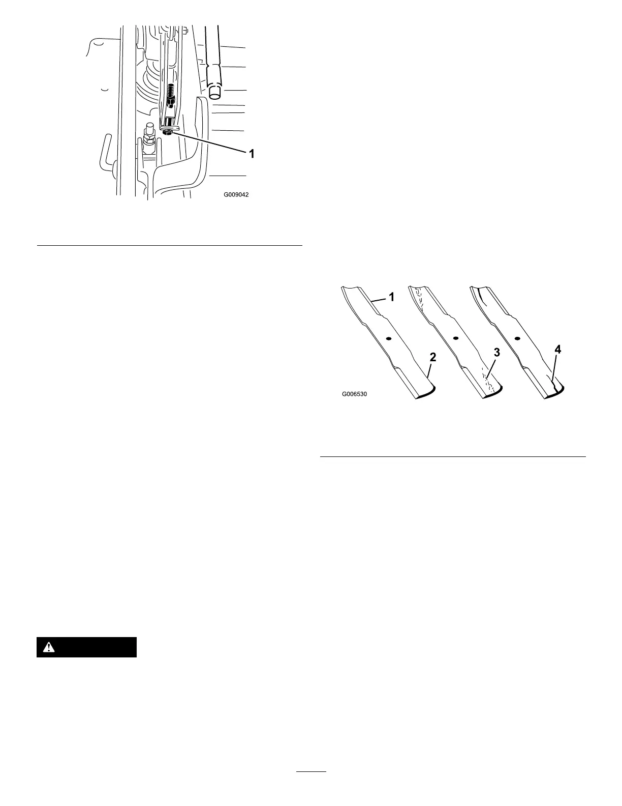
Figure88
1.Singlepointadjustmentbolt
11.Tightenthe2boltsatthebottomoftheheight-of-cut
plate(Figure87).
Note:Inmostconditions,ensuretheback,bladetipis
adjusted6.4mm(1/4inch)higherthanthefront.
12.Torquethe2boltsto37to45N∙m(27to33ft-lb).
13.Onbothsidesofthedeck,measurefromthelevel
surfacetothebacktipoftheblade(positionB)as
showninFigure85.
Note:Themeasurementshouldread8.3cm(3-1/4
inches)
14.Fine-tunethescrewadjusterbyturningittoget8.3
mm(3-1/4inches)height(Figure86).
Note:Toincreasetheheight,turntheadjustmentnut
clockwise;todecrease,turncounterclockwise.
15.Measureuntilall4sidesarethecorrectheight.
16.Tightenallthenutsonthedeck-lift-armassemblies.
ServicingtheCuttingBlades
Important:Therightbladeonthismowerdeckis
counter-rotatingandusesaleftthreadedbladebolt.Use
Figure92forthecorrectplacementofthemowerblades.
Maintainsharpbladesthroughoutthecuttingseasonbecause
sharpbladescutcleanlywithouttearingorshreddingthegrass
blades.Tearingandshreddingturnsgrassbrownattheedges,
whichslowsgrowthandincreasesthechanceofdisease.
WARNING
Awornordamagedbladecanbreak,andapiece
ofthebladecouldbethrownatyouorbystanders,
resultinginseriouspersonalinjuryordeath.
•Inspectthebladesperiodicallyforwearor
damage.
•Replaceawornordamagedblade.
BeforeInspectingorServicingthe
Blades
1.Parkthemachineonalevelsurface,disengagethe
blade-controlswitch(PTO),andsettheparkingbrake.
2.TurntheignitionkeytoOFF.Removethekey,and
disconnectthesparkplugwiresfromthesparkplugs.
InspectingtheBlades
ServiceInterval:Beforeeachuseordaily
1.Inspectthecuttingedges(Figure89).
2.Iftheedgesarenotsharporhavenicks,removeand
sharpentheblade;refertoRemovingtheBlades(page
60)andSharpeningtheBlades(page61).
3.Inspecttheblades,especiallyinthecurvedarea.
4.Ifyounoticeanycracks,wear,oraslotforminginthis
area,immediatelyinstallanewblade(Figure89).
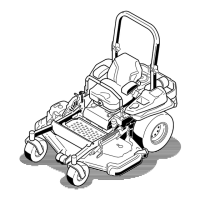
Figure89
1.Cuttingedge3.Wear/slotforming
2.Curvedarea4.Crack
CheckingforBentBlades
1.Disengagetheblade-controlswitch(PTO),movethe
motion-controlleverstotheNEUTRAL-LOCKposition,
andsettheparkingbrake.
2.Shutofftheengine,removethekey,andwaitforall
movingpartstostopbeforeleavingtheoperating
position.
3.Rotatethebladesuntiltheendsfaceforwardand
backward(Figure90).
4.Measurefromalevelsurfacetothecuttingedge,
positionA,oftheblades(Figure90).Notethis
dimension.
59