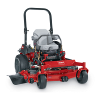
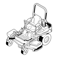
Figure26
1.Anti-scalproller4.Flangenut
2.Spacer
5.Bolt
3.Bushing
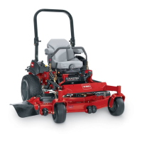
Figure27
1.Anti-scalproller3.Flangenut
2.Bushing4.Bolt
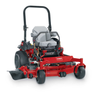
Figure28
1.Anti-scalproller4.Flangenut
2.Spacer
5.Bolt
3.Bushing
AdjustingtheFlowBafeCam
Locks
Thisprocedureisapplicableonlytomachineswiththeow
bafelocks.Certainmodelswillhavenutsandboltsin-place
oftheowbafelocksandcanbeadjustedthesame.
Themowerdischargeowcanbeadjustedfordifferenttypes
ofmowingconditions.Positionthecamlocksandbafeto
givethebestqualityofcut.
1.Disengagethebladecontrolswitch(PTO),movethe
motioncontrolleverstotheneutrallockedposition,
andsettheparkingbrake.
2.Stoptheengine,removethekey,andwaitforallmoving
partstostopbeforeleavingtheoperatingposition.
3.Toadjustthecamlocks,swingtheleveruptoloosen
thecamlock(Figure29).
4.Adjustthebafeandcamlocksintheslotstothe
desireddischargeow.
5.Swingtheleverbackovertotightenthebafeandcam
locks(Figure29).
6.Ifthecamlocksdonotlockthebafeintoplaceorit
istootight,loosentheleverandthenrotatethecam
lock.Adjustthecamlockuntilthedesiredlocking
pressureisachieved.
Figure29
1.Unlocklever
3.Positionthebafe
2.Rotatethecamlockto
increaseordecrease
lockingpressure
4.Locklever
25