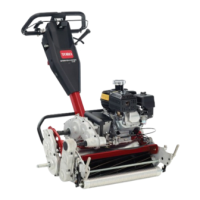
Figure 5
1. Left handle end
3. Pivot pin
2. Support arm
4. Locknut
3. Squeeze the handle ends inw ard and install them
on the ste p of the pi v ot pin ( Figure 5 ).
4. Secure the handle to the capscrew and pi v ot pin
with the flang e loc k n ut ( Figure 5 ).
5. Locate cable tie loosely securing throttle cable to
wire har ness . P osition cable tie appro ximately one
inc h behind transmission and tighten cable tie .
Step
2
Adjusting the Handle
No Parts Required
Procedure
1. R emo v e hair pin cotters from ring pins on eac h side
of mo w er ( Figure 6 ).
Figure 6
1. Ring pins
2. W hile suppor ting handle , remo v e ring pins from
eac h side and raise or lo w er handle to desired
operating position ( Figure 6 ).
3. R einstall ring pins and hair pin cotters .
Step
3
Installing the Transport
Wheels
Parts needed for this step:
2
Transport wheels (Optional Transport Wheel
Kit, Model 04123)
Procedure
1. Push kic k stand do wn with foot and pull up on
handle suppor t until kic k stand has rotated forw ard,
o v er center ( Figure 7 ).
10