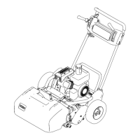
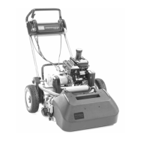
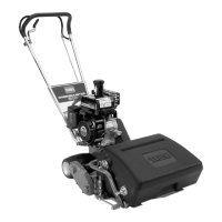
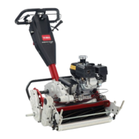
Figure 49
1. Bedbar adjusting screw
3. Tilt mo w er on bac k to expose bedknife and reel.
4. At one end of reel, inser t a long strip of newspaper
betw een reel and bedknife ( Figure 50 ). W hile
slo wly rotating reel forw ard, tur n bedbar adjusting
screw cloc kwise (on same end of reel) ( Figure 49 ),
one clic k at a time , until paper is pinc hed lightly ,
when inser ted from the front, parallel to the
bedknife . A slight drag will be noted as the paper
is pulled.
Figure 50
Note: Eac h time adjusting screw is rotated one
clic k cloc kwise , bedknife mo v es .0007 in. closer to
reel. Do not o v er tighten the adjusting screws .
5. Chec k for light contact at other end of reel using
paper and adjust as required.
6. After adjustment is accomplished, c hec k to see if
reel can pinc h paper when inser ted from the front
and cut paper when inser ted at a right angle to the
bedknife ( Figure 50 ). It should be possible to cut
paper with minim um contact betw een the bedknife
and the reel blades . Should ex cessi v e reel drag
be evident it will be either necessar y to bac klap
or reg rind the cutting unit to ac hiev e the shar p
edg es needed for precision cutting (see T oro reel
shar pening man ual).
Adjusting the Height of Cut
1. Adjust rear roller brac k ets ( Figure 51 ) to upper
or lo w er position de pending on desired height of
cut rang e .
• T he upper position (factor y setting) is used
when height of cut settings rang e from 1/16
to 5/32".
• T he lo w er position is used when height of cut
settings rang e from 1/8" to 19/64".
Figure 51
1. Rear roller bracket 3. Locknut
2. Height-of-cut arm 4. Adjusting screw
2. V erify that rear roller is lev el and that bedknife
to reel contact is cor rect. Tip mo w er on bac k to
expose front and rear rollers and bedknife .
3. Loosen loc kn uts securing height-of-cut ar ms to
cutting unit side plates ( Figure 51 ).
4. Loosen n ut on g aug e bar ( Figure 52 ) and set
adjusting screw to desired height-of-cut. Distance
betw een bottom of screw head and face of bar is
height-of-cut.
Figure 52
1. Gauge bar
3. Nut
2. Height adjusting screw
5. Hook screw head on cutting edg e of bedknife and
rest rear end of bar on rear roller ( Figure 53 ).
30
 Loading...
