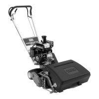
1. Mo v e traction control to Diseng ag ed position.
2. T o increase cable tension, loosen front cable jam
n ut and tighten bac k cable jam n ut ( Figure 42 )
until a force of 12-16 lb . is required to eng ag e
traction control.
Measure the force at the control knob .
Figure 42
1. Traction cable 2. Service/parking brake cable
3. Tighten front cable jam n ut.
4. Chec k control operation.
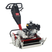
Adjusting the Reel Control
If reel control does not eng ag e or it slips during
operation, an adjustment is required.
1. Mak e sure traction control is properly adjusted;
refer to Adjusting the T raction Control, pag e .
2. T o increase cable tension, loosen front cable jam
n ut and tighten bac k cable jam n ut ( Figure 43 )
(located on top of g ear bo x) until the reel cable
force adds 7 to 10 lbs . of additional handle force
measured at the control knob .
Note: If traction control handle force is 12 lbs .,
the combined traction and reel force should be 19
to 22 lbs .
Figure 43
1. Reel control cable
3. Tighten front cable jam n ut.
4. Chec k control operation.
Cutting Unit
Maintenance
Separating the Cutting Unit
from the Traction Unit
1. Place the mo w er on its dr ums on a lev el surface .
2. Lo w er kic k stand. Inser t a 1/4" dia. pin or
equi v alent into frame hole abo v e kic k stand
mounting bolt ( Figure 44 ).
Figure 44
1. Kick stand 2. 1/4" Pin
3. R emo v e g rass bask et.
4. R emo v e (2) capscrews securing cutting unit pi v ot
ar ms to traction unit frame tube ( Figure 45 ).
Figure 45
1. Cutting unit pivot arms
3. Capscrews
2. Traction unit frame tube
5. R otate pi v ot ar ms forw ard ( Figure 45 ) and rest
traction unit on restrained kic kstand.
6. Pull cutting unit forw ard about 2 in. (51 mm) and
then to the right to diseng ag e the transmission
coupling ( Figure 46 ).
28