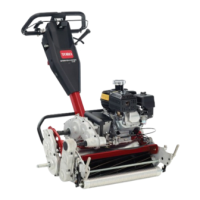
Figure 46
1. Transmission coupling
7. R ev erse procedure to install cutting unit.
Leveling the Rear Roller to
the Reel
1. P osition cutting unit on a flat, lev el surface
preferably a precision g round surface plate .
2. Place a 1/4 in. (6.4 mm) or thic k er plate under the
reel blades and ag ainst front edg e of bedknife .
Note: Be sure the plate co v ers the full length of
the reel blades and three blades contact.
3. Fir mly press do wn on cutting unit and maintain
pressure on rear roller . T r y inser ting a piece of
paper under eac h end of the roller . If the g ap is
g reater than the piece of paper , on either end, an
adjustment ma y be required, proceed to ste p 4 .
4. Loosen loc kn uts securing right rear roller brac k et
to cutting unit side plate ( Figure 47 ).
Figure 47
1. Right rear roller bracket 2. Locknuts
5. W hile holding reel securely on plate and
maintaining pressure on rear roller , rotate lo w er
right roller mounting bolt ( Figure 48 ).
T his mounting bolt has an offset, whic h when
rotated, acts as an eccentric (cam) to raise or lo w er
the roller . T here is an I.D . dot whic h denotes the
offset of the bolt. Dot indicates in whic h direction
right end of roller mo v es when bolt is tur ned and
should alw a ys be in the rear half of the arc as
sho wn in Figure 48 .
Figure 48
1. Eccentric bolt
Note: If additional adjustment is required, re place
the screw on the left-hand brac k et with another
eccentric bolt, P ar t No . 105-3833. Ensure both
rear roller brac k ets are in the same hole .
6. T o v erify if roller is lev el, tr y inser ting a piece of
paper under eac h end of roller .
7. W hen roller is lev el, tighten n uts securely .
Adjusting the Bedknife to
the Reel
Bedknife to reel adjustment is accomplished b y
loosening or tightening bedbar adjusting screws ,
located on top of mo w er .
1. P osition mac hine on a flat, lev el w ork surface .
2. Mak e sure reel contact is remo v ed b y tur ning
bedbar adjusting screws countercloc kwise
( Figure 49 ).
29
 Loading...
