AssemblingtheDriveshafttothe
Flywheel-AdapterPlate
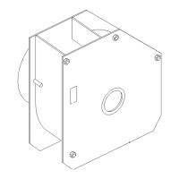
1.Assemblethedriveshafttotheywheel-adapter
plateandbackupplate(Figure6)withthe6
capscrew(3/8x1inch)and6angelocknut
(3/8inch).
g266464
Figure6
1.Flangelocknut(3/8inch)
4.Backupplate
2.Driveshaft5.Capscrew(3/8x1inch)
3.Flywheel-adapterplate
2.Torquethecapscrewsandlocknutsto37to43
N∙m(28to32ftlb).
InstallingtheDriveshaft
andFlywheel-AdapterPlate
AssemblingtheDriveshaftand
Flywheel-AdapterPlatetothe
Engine
Ownersuppliedmaterial:Permatex®high-strength
threadlockingcompoundPartNo.24010
1.Applyacoatofthespeciedhigh-strength
threadlockingcompoundontothethreadsofthe
8ange-headcapscrew.
2.Assemblethe2backupringsand
ywheel-adapterplatetotheywheelof
theenginewiththe8ange-headcapscrewas
showninFigure7.
g266463
Figure7
1.Flange-headcapscrew
3.Flywheel(engine)
2.Flywheel-adapterplate4.Backuprings
3.Torquetheange-headcapscrewsto23to28
N∙m(17to21ftlb).
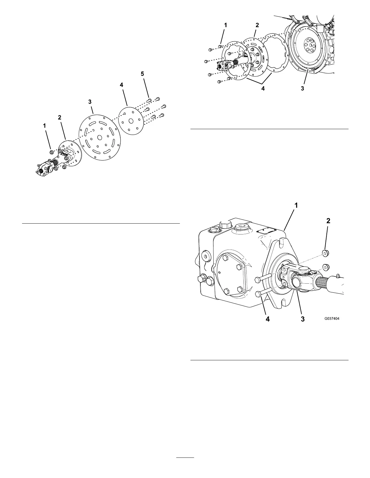
AssemblingtheDriveshafttothe
HydraulicPump
1.Alignthesplinesofthedriveshaftyoketothe
splinesofthehydraulic-pumpshaft(Figure8).
g037404
Figure8
1.Hydraulicpump
3.Driveshaftyoke
2.Flangenut(2)4.Bolt(2)
2.Slidethedriveshaftyokeontothehydraulic-pump
shaft(Figure8),andassembletheyoketothe
shaftwiththe2capscrewsand2angenutthat
youremovedinstep1RemovingtheDriveshaft
andFlywheel-AdapterPlate(page2).
3.Torquethelocknutsto20to25N∙m(175to225
in-lb).
4
 Loading...