3
InstallingtheFlasher
Module
Partsneededforthisprocedure:
1Flashermodule
1Wireharness
1
Switch
1Auxiliary-brakedecal
Procedure
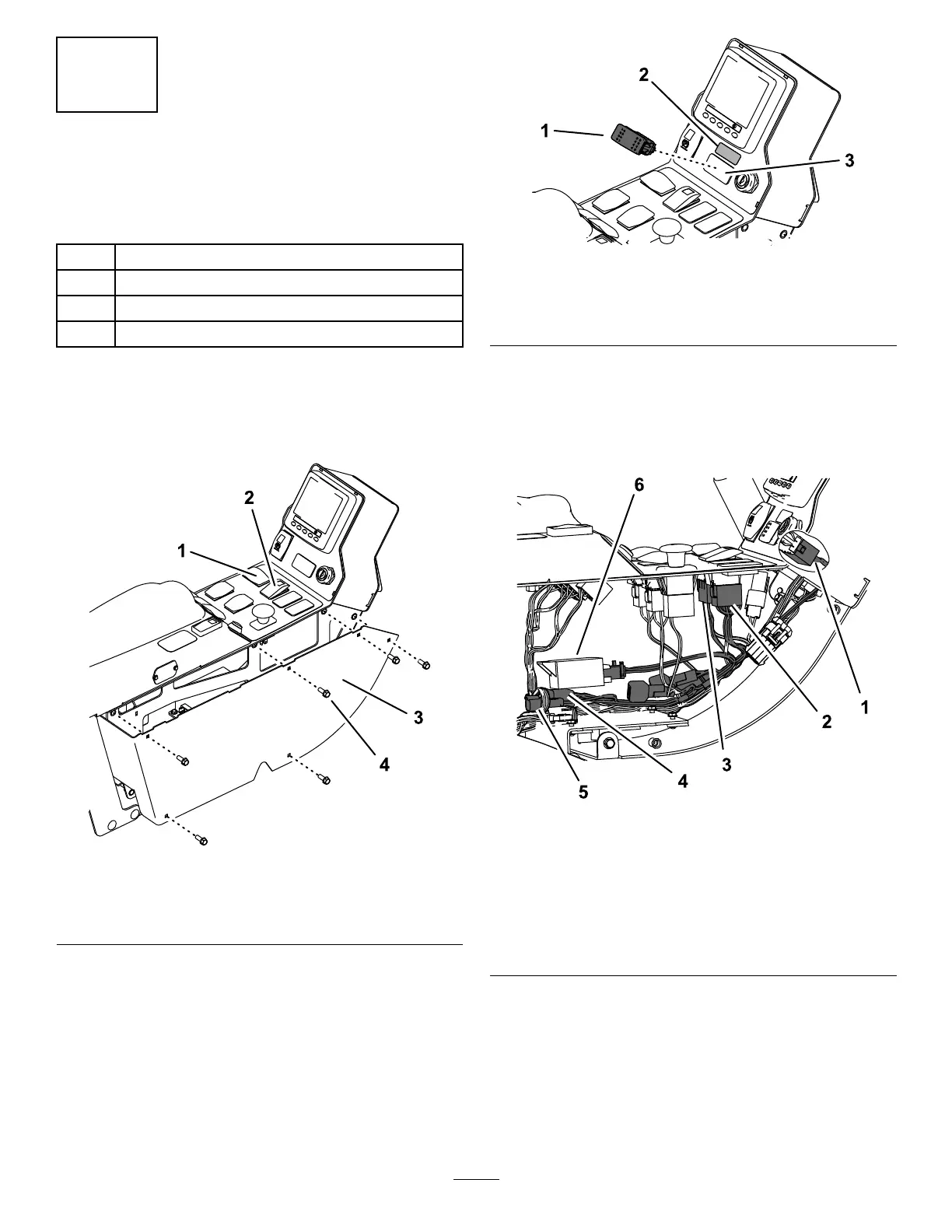
1.Removethe6boltsfromtheconsoleandremovethe
panel(Figure3).
g186692
Figure3
1.Turn-signalswitch3.Panel
2.Hazardswitch
4.Bolt(6)
2.Disconnecttheconnectorsfromthehazardswitchand
turn-signalswitch(Figure3).
3.Removetheknockoutfromthecontrolpaneland
installtheswitch(Figure4).
g186717
Figure4
1.Switch
3.Knockout
2.Auxiliary-brakedecal
4.Adheretheauxiliary-brakedecalabovetheswitch
(Figure4).
5.Connectthenewwireharnesstotheashermodule,
hazardswitch,turn-signalswitch,andauxiliary-brake
switch(Figure5).
g186719
Figure5
1.Connecttothe
auxiliary-brakeswitch.
4.Connecttothemainwire
harness.
2.Connecttotheturn-signal
switch.
5.ConnecttotheEULight
Powerconnectoronthe
mainwireharness.
3.Connecttothehazard
switch.
6.Flashermodule
6.Connectthewireharnesstothemachinemainwire
harnessinsidetheconsole(Figure5).
7.Installthepanel(Figure3).
4

 Loading...


