g033146
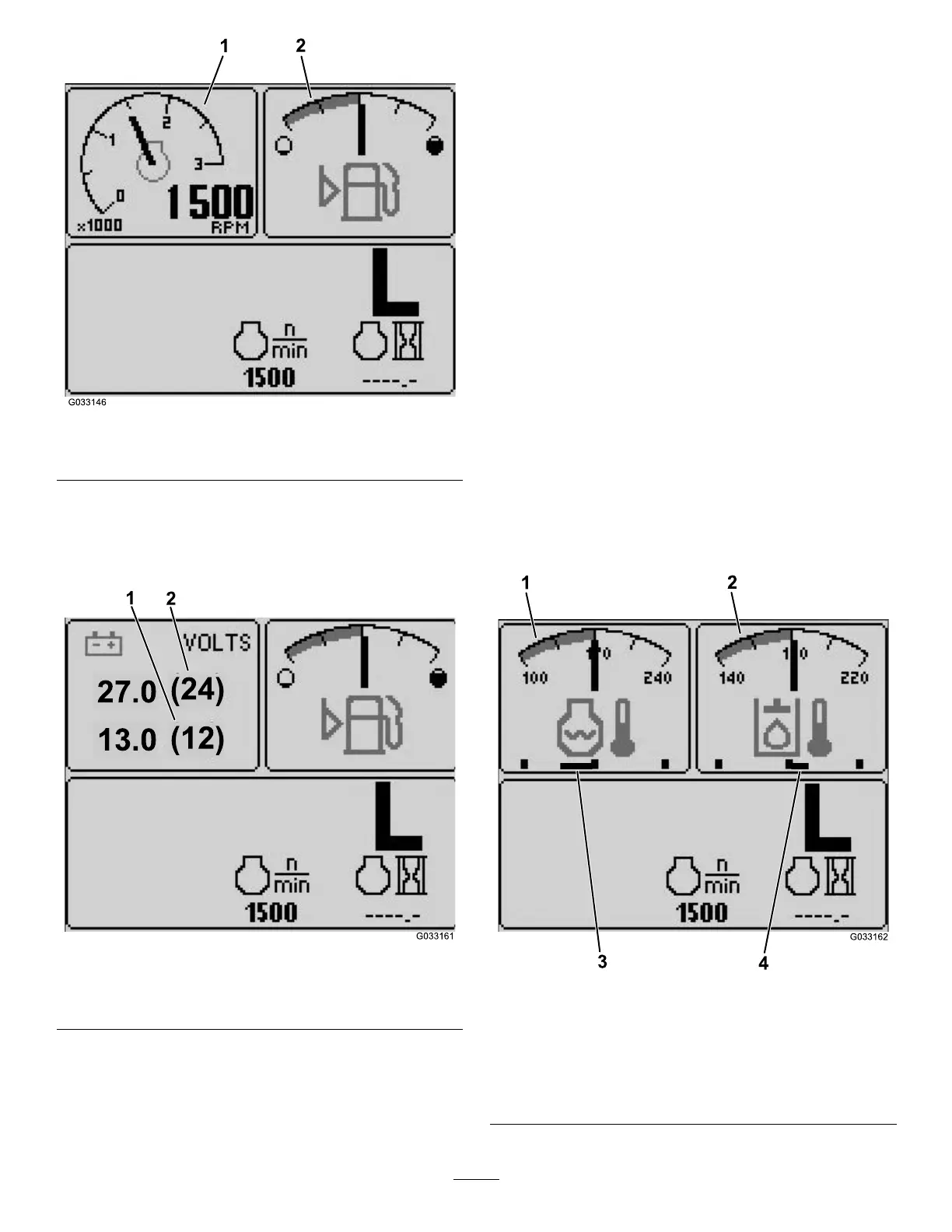
Figure3
1.Tachometer2.Fuel-levelindicator
•12Vbattery-voltageindicator—top,leftscreen
(Figure4)
•24Vbattery-voltageindicator—top,leftscreen
(Figure4)
g033161
Figure4
1.12Vbattery-voltage
indicator
2.24Vbattery-voltage
indicator
•Hydraulic-uid-temperatureandfanindicator—top,
rightscreen(Figure5)
Note:Inthefollowingexample,the
hydraulic-uid-coolingfansarerunningat25%
speedintheforwarddirection.
•Engine-coolant-temperatureandfan
indicator—top,leftscreen(Figure5)
Note:InexampleFigure5,theengine-coolant
fansarerunningat50%speedinthereverse
direction.
Thisdisplay(Figure1)indicatesfanspeedand
direction.Thefanspeediscontrolledbythe
hydraulic-uidtemperatureortheengine-coolant
temperature,andautomaticallyreversesas
needed.Areversecycleautomaticallyinitiatesto
helpblowdebrisofftherespectivehoodscreen,
wheneitherthetemperatureoftheenginecoolant
orthehydraulicuidreachesacertainpoint.
Additionally,theradiatorfansperformareverse
cycleevery21minutesregardlessofthecoolant
temperature.
Fandirectionisalsoindicatedonthe
engine-coolant-temperaturescreenandthe
hydraulic-uid-temperaturescreen.Ifthebaris
totherightofthemidpointhashmark,thefans
arerunningintheforwarddirection.Ifthebaristo
theleftofthemidpointhashmark,thefansare
runninginthereversedirection(Figure5).
g033162
Figure5
1.Engine-coolant
temperatureindicator
3.Engine-coolantfans
runningat50%speedin
thereversedirection
2.Hydraulic-uid
temperatureindicator
4.Hydraulic-uidcooling
fansrunningat25%speed
intheforwarddirection
3
 Loading...


