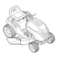
Figure 3
AttachingthePTOLever
NOTE: Your tractor's PTO lever may have already be
attached at the factory.
ToolsRequired
(1) 1/2" socket wrench
1. Position the PTO lever on the PTO shaft and
secure with the hex lock nut. See Figure 4.
Cap_
\
HexNut _ o
PT0 Lever
PT0
) Shaft
.
\
' ,;"..... _' 'I I
-- -' ,i .... F!gure
4
Place the .PTOlever cap over the hex nut and push
downward until jt '_'clicks"into place.
ShippingBraceRemoval
WARNING: Make sure the riding mower's
engine is off, set the parking brake and
remove the ignition key before removing the
shipping brace.
• Locate the shipping brace, if present, and warning
tag found on the right side of the cutting deck. See
Figure 5.
° While holding the discharge chute with your left
hand, remove the shipping brace with your right
hand by grasping it between your thumb and index
finger and rotating it clockwise.
,\
WARNING: The shipping brace, used for
packaging purposes only, must be removed
and discarded before operating your riding
mower.
WARNING: The mowing deck is capable of
throwing objects. Failure to operate the riding
mower without the discharge cover in the
proper_ii_lSerating':positioncould result' in
-serious-. personal injury-and/or properly',
damage.
<.TirePressure:" :,
, ,,:.WARNING: Never exceed the maximum
.inflation pressure shown on the sidewall of the
' tire.
<i "L._'I, i ,!- i ._. .
The tires on your unit may be over-inflated for shipping
purposes. Reduce the tire pressure before operating
!he.tractor.,Recomm.e0_!e.doncerat!ng tire:!0ress ure.is..<.
approximately 10 p.s.i, for the rear tires and 14 p.s.i, for
the front tires. Check sidewall of tire for maximum p.s.i.
11!
 Loading...