ENGINE REMOVAL / INSTALLATION
3 - 2 Snow Commander Service Manual
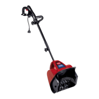
Figure 19
3428-0227
6. Disconnect the primer line from the primer bulb
and the wires from the ignition switch (Figure 20).
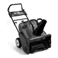
Figure 20
DSC-0138
7. On electric start models, remove three screws
connecting the switch box to the control panel
support (Figure 21).
Figure 21
3428-0228
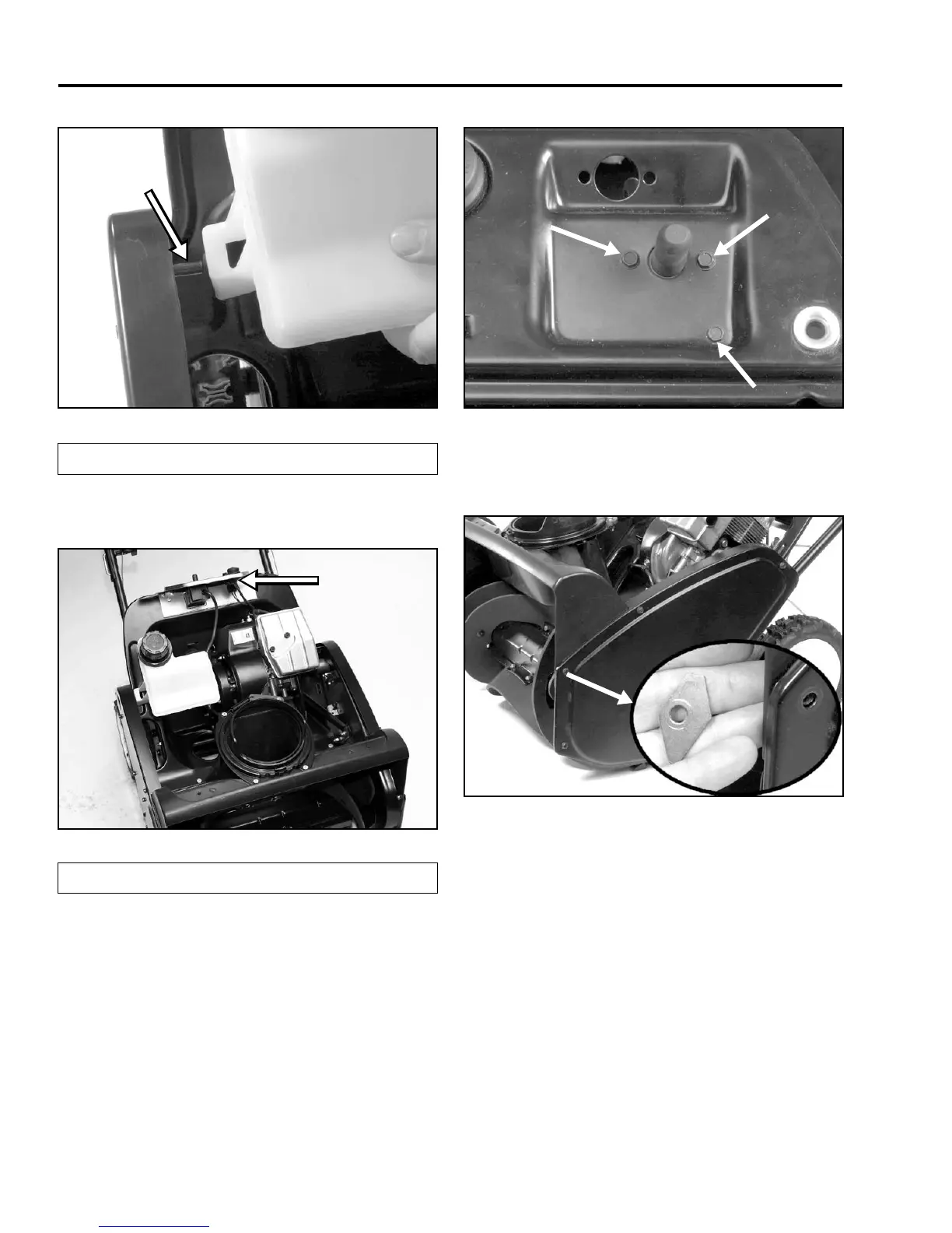
8. Remove the belt cover (3 bolts and 2 screws)
(Figure 22). Some models were built with a
diamond shaped washer.
Figure 22
3428-0229-2
9. Remove the belt. Push the idler arm down as far
as it will go. Measure the distance between the
idler pulley and engine pulley at its closest point
(Figure 23). Make a note of this distance as it will
be needed during assembly.
(A) Support Pin
(A) Primer and Ignition Switch
A
A