5.Loosentheadjustmentboltsonall4cornersso
thatthedeckissittingsecurelyonall4blocks
(Figure60).
g299014
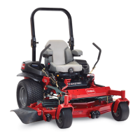
Figure60
1.Deck-liftarm
3.Deckhanger
2.Deckpin4.Adjustmentbolt
6.Ensurethatthedeckpinsareatthetopofthe
slotinthedeckhangers(Figure60).
7.Tightenthe4adjustmentbolts(Figure60).
8.Ensurethattheblockstsnuglyunderthedeck
skirtandthatallboltsaretight.
9.Verifythatthedeckislevelbycheckingthe
side-to-sidelevelandfront-to-rearbladeslope;
repeatthedecklevelingprocedureifnecessary.
RemovingtheMowerDeck
1.Parkthemachineonalevelsurface,disengage
theblade-controlswitch(PTO),andmovethe
motion-controlleversoutwardtothePARK
position..
2.Shutofftheengine,removethekey,andwait
forallmovingpartstostopbeforeleavingthe
operatingposition.
3.Lowertheheight-of-cutlevertothelowest
position.
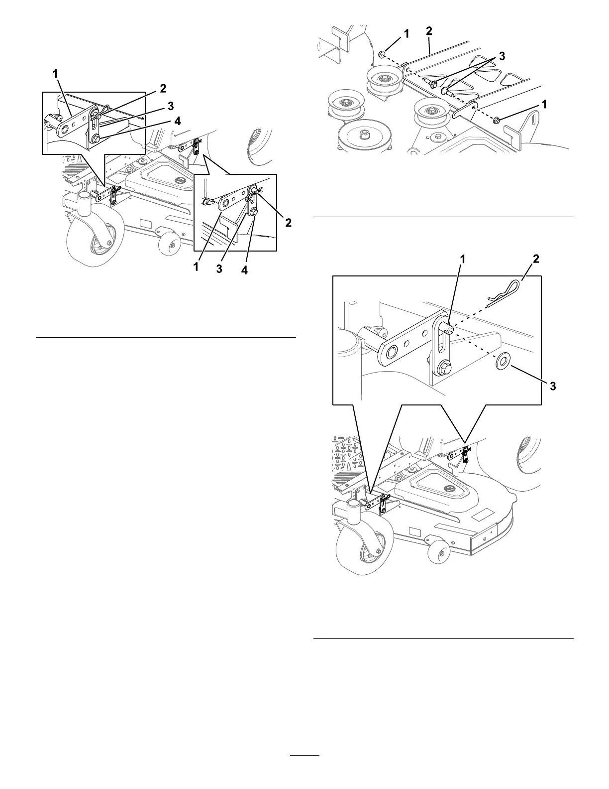
4.Attherearofthemowerdeck,removethe2
shoulderboltsandnutssecuringthedecktothe
pivotpan(Figure61).
g299079
Figure61
1.Nut
3.Shoulderbolt
2.Pivotpan
5.Atall4cornersofthedeck,removethehairpin
cotterandwasherfromthedeckpin(Figure62).
g299015
Figure62
1.Deckpin3.Washer
2.Hairpincotter
6.Raisetheheightofcuttothehighestposition.
7.Removethebeltfromtheclutchpulleyonthe
engine.
8.Slidethemoweroutfromunderneaththe
machine.
Note:Retainallpartsforfutureinstallation.
41
 Loading...