LevelingtheMowerDeck
Checktoensurethemowerdeckislevelanytimeyouinstall
themowerorwhenyouseeanunevencutonyourlawn.
Themowerdeckmustbecheckedforbentbladespriorto
leveling;anybentbladesmustberemovedandreplaced.Refer
totheCheckingforBentBladesprocedurebeforecontinuing.
Themowerdeckmustbeleveledside-to-siderstthenthe
fronttorearslopecanbeadjusted.
Requirements:
•Themachinemustbeonalevelsurface.
•Allfourtiremustbeproperlyinated.RefertoChecking
theTirePressureintheDriveSystemMaintenance
section.
Side-to-SideLeveling
1.Parkthemachineonalevelsurfaceanddisengagethe
bladecontrolswitch.
2.Movethemotioncontrolleversoutwardtothepark
position,stoptheengine,removethekey,andwaitfor
allmovingpartstostopbeforeleavingtheoperating
position.
3.Settheheight-of-cutlevertomiddleposition.
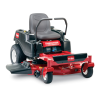
4.Carefullyrotatethebladessothattheyareallsideto
side(Figure49).
Figure49
1.Bladessidetoside
3.Outsidecuttingedges
2.Sailareaofblade4.Measurefromthetipofthe
bladetotheatsurface
here
5.Measurebetweentheoutsidecuttingedgesandtheat
surface(Figure49).Ifbothmeasurementsarenot
within3/16inch(5mm),anadjustmentisrequired;
continuewiththisprocedure.
6.Supporttheweightofmowerdeckbyplacingwood
blocksundertheedgesofthedeck.
Note:Avoidplacingthesupportsunderanyanti-scalp
rollersifpresentonthedeck.
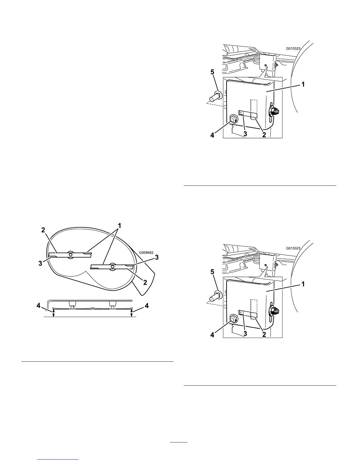
7.Movetotheleftsideofthemachine.Checkiftheside
carriageboltisinthexedorslottedposition(Figure
50).
Figure50
1.Hangerbracket
4.Sidelockingnut
2.Slottedadjustment
position
5.Sidecarriagebolt
3.Fixedposition
8.Ifthesidecarriageboltisinthexedposition,remove
thesidecarriageboltandsidelockingnutfromthe
xedpositionandinstallitintotheslottedadjustment
position(Figure51).
Iftheboltisintheslottedposition,thecarriagebolt
andsidelockingnutdonotneedtoberemoved.
Figure51
1.Hangerbracket
4.Sidelockingnut
2.Slottedadjustment
position
5.Sidecarriagebolt
3.Fixedposition
9.Loosentherearlockingnutonthehangerbracketjust
enoughtomovethebracket(Figure52).
35
 Loading...