EasyManuals Logo

Toshiba B-SX6T Series Option Installation Manual

Toshiba B-SX6T Series
31 pages
To Next Page IconTo Next Page
To Previous Page IconTo Previous Page
Page #5 background imageLoading...
Page #5 background image
INSTALLATION PROCEDURE FOR OPTIONAL EQUIPMENT
EO15-33002
1. Cutter Module: B-SX208-QM-R
1- 3
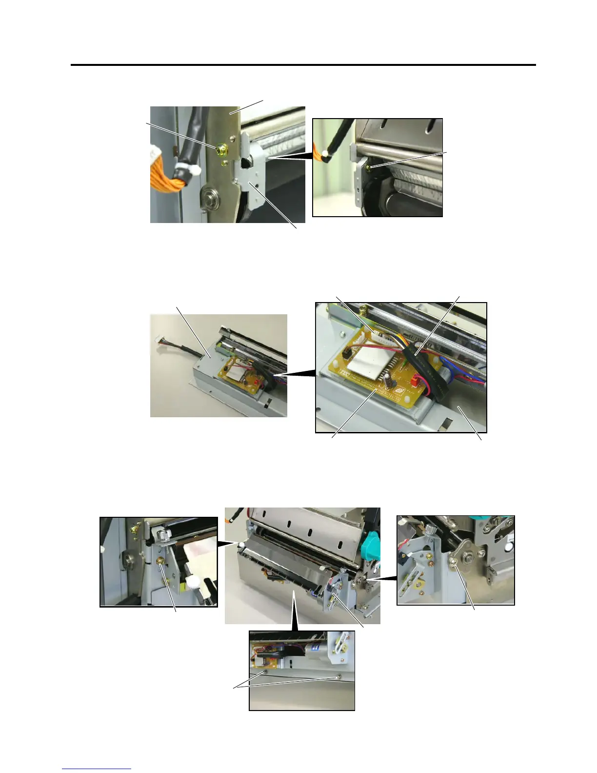
6. Attach the cutter support plate to the main frame with the two screws (FL-4x6).
7. Connect the cutter harness to CN3 on the cutter interface PC board through the opening of the cutter
unit.
8. Install the cutter unit with the supplied four screws (cuter attaching screws, SM-4x6 and FL-4x6). When
installing the cutter unit, make sure that the cutter guide does not contact with the platen. If so, a print
failure or noise may occur.
FL-4x6 Screw
FL-4x6 Scre
w
Cutter Support Plate
Main Frame
Cutter Interface PC Board
CN3
Cutter Unit
Cutter Harness
Cutter Unit
FL-4x6 Screw
SM-4x6 Screw
Cutter Attaching Scre
w
Opening

Other manuals for Toshiba B-SX6T Series

Questions and Answers:

Question and Answer IconNeed help?

Do you have a question about the Toshiba B-SX6T Series and is the answer not in the manual?

Toshiba B-SX6T Series Specifications

General IconGeneral
Print TechnologyThermal Transfer / Direct Thermal
Media Thickness0.06 mm to 0.2 mm
ConnectivityUSB, Serial, Ethernet
Operating System CompatibilityWindows
BarcodesCode 39, Code 128, Interleaved 2 of 5
2D CodesPDF417, Data Matrix, QR Code, MaxiCode
Print Resolution203 dpi, 300 dpi

Related product manuals