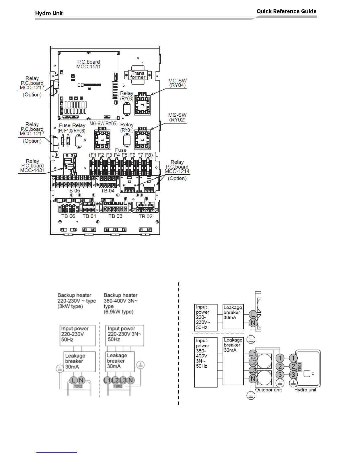
Fuses (AC250V T30A):
F1&F2: Hot water cylinder electric heater supply
F3&F4: Back up heater 1 (3kW)
F5&F6: Back up heater 2 (3kW)
F7&F8: Back up heater 3 (3kW)
Fuses (AC250V T3.15A)
F9&F10: A rated water pump
PCB’s:
MCC-1214: TCB-PCMO3E (optional input PCB)
MCC-1217: TCB-PCIN3E (optional output PCB)
MCC-1431: Relay PCB for control of second
water pump, 2 way valve and booster heater
outputs
MCC-1511: Main hydro unit control / interface
PCB
Contactors & Relays:
RY01: Interlock relay – flow switch / back up
heater circuit
RY02: Power contactor for back up heater supply
RY03: Control relay for back up heater s 2 & 3
operation
RY04: Power contactor for back up heater supply
RY05: Power contactor for hot water cylinder
electric heater supply
RY06: Control relay for mixing valve (2 zone)
operation

 Loading...