34 HX7+ ASD Quick Start Guide
Typical Connection Diagram
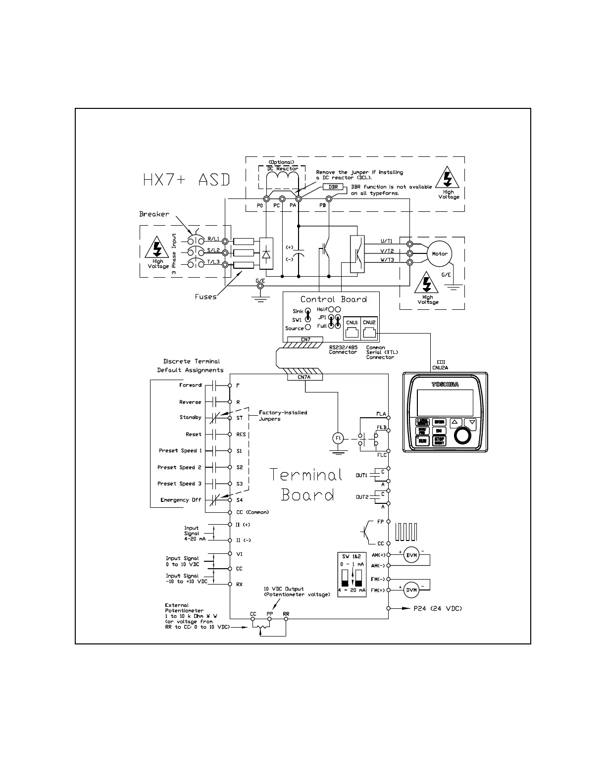
Figure 20. HX7+ ASD Typical Connection Diagram.
Note: The VI, RX, and RR analog input terminals are referenced to CC.
The AM, FM, and II analog input terminals are referenced to the respective negative
terminals.
The FP, PP, and P24 output terminals are referenced to CC.
Note: See Figure 2 on pg. 18 for an alternative ST-to-CC activation configuration.
Note: When connecting multiple wires to the PA, PB, PC, or PO terminals, do
not connect a solid wire and a stranded wire to the same terminal.

 Loading...


