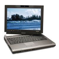
4.25 LCD unit/FL inverter 4 Replacement Procedures
7. Remove the following screws securing the LCD unit.
• M2.0×4.0B BIND screw ×4
8. Raise the top edge of the LCD unit on the display cover.
NOTE: When putting the LCD unit on the display cover, lay a mat or something under the
LCD unit to protect the computer and the LCD from a scratch or breakage.
M2.0x4.0B BIND
LCD unit
M2.0x4.0B BIND
Figure 4-45 Removing the LCD unit (1)
PORTEGE M400 Maintenance Manual (960-541) [CONFIDENTIAL] 4-65
Get user manuals: See SafeManuals.com
 Loading...