Do you have a question about the Toshiba RAS-10BKV-E1 and is the answer not in the manual?
Safety guidelines for power supply cord and connecting cable.
Precautions for R410A refrigerant and installation.
Instructions for safe disconnection from the power supply.
Detailed technical specifications for indoor and outdoor units.
Graphs showing operational characteristics based on compressor speed.
Charts illustrating capacity changes with outdoor temperature.
Essential safety precautions for handling R410A refrigerant.
Guidelines for installing refrigerant piping, including materials and joints.
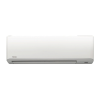
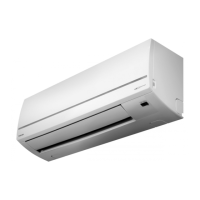
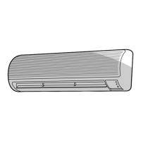
Exploded view and dimensions of the indoor unit components.
Exploded view and dimensions of the outdoor unit components.
List of electrical parts for the indoor unit with specifications.
List of electrical parts for the outdoor unit with specifications.
Schematic diagram illustrating the refrigerant flow within the system.
Block diagram showing the control functions of the indoor unit.
Block diagram illustrating the outdoor unit's control system.
General overview of the air conditioner's control system and logic.
Detailed explanation of various operation modes and functions.
Procedure for setting and managing the auto restart feature.
Details on remote controller parts and operational functions.
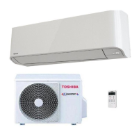
Visual guide for installing indoor and outdoor units.
Information on installation steps and optional parts.
Specific installation guidelines for the indoor unit.
Specific installation guidelines for the outdoor unit.
Instructions for electrical connections and power supply.
Various procedures including gas leak test and remote control settings.
Initial checks for power supply and basic operation status.
Interpreting error codes indicated by indoor unit LEDs.
Using the remote controller for detailed self-diagnosis.
Troubleshooting based on specific operational symptoms.
Procedures for checking key components.
Methods for checking internal parts like P.C. boards and sensors.
Steps to diagnose the outdoor fan motor's condition.
Procedures for replacing main parts of the indoor unit.
Procedures for replacing main parts of the outdoor unit.
Exploded view and parts list for the indoor unit.
Exploded view and parts list for Outdoor Unit RAS-10BAV-E1.
Exploded view and parts list for Outdoor Unit RAS-13BAV-E1.
| Brand | Toshiba |
|---|---|
| Model | RAS-10BKV-E1 |
| Category | Air Conditioner |
| Language | English |