EN
ES
FR
IT
DE
PT
PL
CZ
RU
CR
HU
TR
NL
GR
SV
FI
NO
DK
RO
BG
EE
LV
SK
SI
7
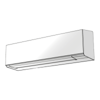
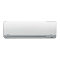
INDOOR UNIT
Installation Place
• Direct sunlight to the indoor unit’s wireless receiver should be avoided.
• The microprocessor in the indoor unit should not be too close to RF
noise sources.
(For details, see the owner’s manual.)
Remote control
• A place where there are no obstacles such as a curtain that may block the
signal from the remote control.
• Do not install the remote control in a place exposed to direct sunlight or
close to a heating source such as a stove.
• Keep the remote control at least 1 m apart from the nearest TV set or
stereo equipment. (This is necessary to prevent image disturbances or
noise interference.)
• The location of the remote control should be determined as shown below.
Cutting a Hole and Mounting
Installation Plate
NOTE
• When drilling a wall that contains a metal lath, wire lath or metal plate, be
sure to use a pipe hole brim ring sold separately.
Cutting a hole
: Pipe hole (
Ø65 mm
)
100 60
(Rear piping)
(Bottom piping)
(Side piping)
45
45
45
45
100
60
100 70
1. After determining the pipe hole position, drill the pipe hole (Ø65 mm) at a
slight downward slant to the outdoor side.
When the installation plate is directly mounted
on the wall
1. Securely fi t the installation plate onto the wall by screwing it in the upper
and lower parts to hook up the indoor unit.
2. To mount the installation plate on a concrete wall with anchor bolts, use
the anchor bolt holes as illustrated in the below fi gure.
3. Install the installation plate horizontally in the wall.
• A place which provides the spaces around the indoor unit as shown in the
diagram.
• A place where there are no obstacles near the air inlet and outlet.
• A place which allows easy installation of the piping to the outdoor unit.
• A place which allows the front panel to be opened.
CAUTION
Failure to fi rmly install the unit may result in personal injury and property
damage if the unit falls.
• In case of block, brick, concrete or similar type walls, make Ø5 mm holes
in the wall.
• Insert clip anchors for appropriate mounting screws 7.
CAUTION
7
Installation plate
(Keep horizontal direction)
Ø5 mm hole
Clip anchor
(local parts)
Mounting screw
Ø4 mm × 25R
Anchor bolt
Projection
15 mm or less
(Side view) (Top view)
* : Axial distance
Reception range
Remote control
Remote
control
Reception range
Indoor unit
80°
90°
7 m
7 m
45°
45°
Mounting the installation plate
(Unit : mm)
(700)
150
230
670
(600)
15
15
590
560
272
15
15
90
(205)
Floor
Wall

 Loading...