Do you have a question about the Toshiba RAS-M10UKV-E3 and is the answer not in the manual?
| Cooling Capacity | 2.5 kW |
|---|---|
| Heating Capacity | 3.2 kW |
| Refrigerant | R410A |
| Power Supply | 220-240V, 50Hz |
| Indoor Unit Weight | 9 kg |
Details technical specifications for indoor and outdoor units, including capacities and electrical characteristics.
Performance data for various indoor unit combinations with an outdoor unit, covering cooling and heating.
Graphs showing cooling/heating current vs. inverter output frequency for different voltage levels.
Charts showing capacity variation based on outdoor temperature for cooling and heating modes.
Charts showing capacity variation based on total pipe length for cooling and heating modes.
Detailed electrical specifications for the outdoor unit, including compressor and fan motor data.
Crucial safety precautions for handling R410A refrigerant during installation and servicing.
Guidelines on piping materials, joints, and processing for R410A systems.
Lists specific tools required for R410A installation and their interchangeability with R22 tools.
Step-by-step guide for recharging refrigerant, including diagrams and precautions.
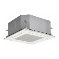
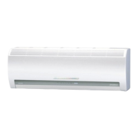
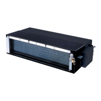
Exploded view and dimensions of the indoor unit, showing major parts and their layout.
Exploded view and dimensions of the outdoor unit, detailing external features and mounting points.
Wiring diagram for the indoor unit, including terminal block connections and color identification.
Wiring diagram for the outdoor unit, detailing component connections and control signals.
List of electrical components and their specifications for the indoor unit.
List of electrical components and their specifications for the outdoor unit.
Diagram illustrating the refrigerant flow and key components in the system for different models.
Operating data (pressure, temperature, speed) for cooling mode across various combinations.
Operating data for heating mode, showing combinations and parameters.
Diagram illustrating the control logic and signal flow for the indoor unit's MCU.
Diagram showing the control logic for the outdoor unit's inverter assembly and MCUs.
Overview of the air conditioner's control system, including indoor/outdoor unit roles.
Explains how compressor motor speed controls cooling capacity via inverter.
Mechanism to prevent indoor heat exchanger freezing during cooling/dry operation.
Details on cooling operation control, including capacity, freezing prevention, and current limits.
Operation details for dehumidifying (DRY) mode, focusing on fan and compressor control.
Description of heating operation control and fan speed adjustments for comfort.
Functionality and setting for automatic restart after power loss or supply interruption.
Detailed explanation of each button and function on the remote control.
Explanation of all symbols and indicators shown on the remote control display.
Critical safety warnings and precautions for installing the air conditioner.
Lists specific tools required for R410A installation and their differences from R22 tools.
General overview of indoor unit installation steps, including accessories and parts.
Guidelines for selecting an appropriate installation location for the indoor unit.
Procedures for cutting wall holes and mounting the indoor unit installation plate.
Detailed steps for connecting the indoor unit's wiring to the terminal block.
Procedures for forming refrigerant pipes and installing the drain hose.
Steps for securely mounting the indoor unit onto the installation plate.
Instructions for ensuring proper drainage slope and connection of the drain hose.
How to set the remote controller selector switch for multi-unit installations.
Steps for verifying correct installation and performing operational tests.
Guidelines for installing the outdoor unit, including placement and securing.
Specific requirements for R410A refrigerant piping materials and dimensions.
Detailed steps and precautions for connecting refrigerant pipes, including flaring.
Procedure for evacuating air from the refrigerant system using a vacuum pump.
Instructions for connecting the power cord and inter-unit wiring.
Steps to check for gas leaks and perform operational tests on the outdoor unit.
How to check for incorrect wiring or piping using LED indicators on the outdoor unit.
Basic checks before detailed troubleshooting, including power and operation confirmation.
Initial diagnosis methods using indoor unit LEDs and remote control.
Interpreting indoor unit LED blinking patterns for fault identification.
Using the remote control in service mode to retrieve check codes for diagnosis.
Step-by-step diagnostic flowcharts based on observed symptoms.
Diagnosing common problems with the indoor fan motor operation.
Procedure to test the functionality of the remote controller.
Troubleshooting steps for wiring issues between indoor and outdoor units.
Guide to interpreting outdoor unit LED displays for fault diagnosis.
Flowchart for diagnosing problems with the outdoor unit's inverter assembly.
Table showing resistance values of various sensors at different temperatures.
Procedures for checking specific indoor unit components like sensors and motors.
Procedures for checking outdoor unit components like compressor and sensors.
Detailed methods for checking capacitors, converter modules, and IGBT modules.
Steps to diagnose if the outdoor fan motor is functioning correctly.
Step-by-step procedures for replacing the front panel, electrical part, and horizontal louver.
Procedures for replacing heat exchanger, cross-flow fan, and base bearing.
Procedure for replacing the microcomputer unit.
Steps for detaching major components of the outdoor unit for access.
Procedure for safely removing and replacing the inverter assembly.
Steps for replacing the main and sub control boards.
Procedure for replacing the outdoor fan motor.
Procedure for replacing the compressor, including refrigerant evacuation.
Procedure for replacing the reactor component.
Procedure for replacing the PMV coil.
Procedures for replacing various temperature sensors in the unit.
Exploded diagram and part number list for the indoor unit.
Exploded diagram and part number list for the outdoor unit.