8-7
INSTALLATION-WIRING DIAGRAMS
SECTION 100-816-208
MARCH 1993
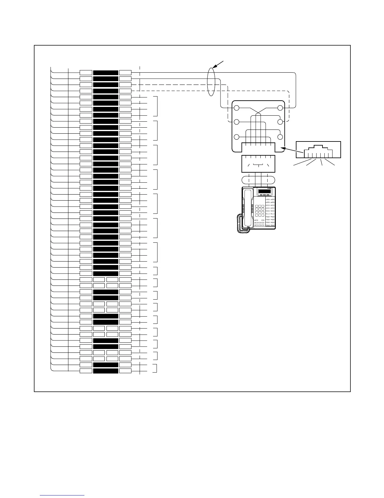
FIGURE 8-2
DK8 MDF WIRING TO KSU AMPHENOL STATION AND RELAY CONNECTIONS
1
2
3
4
5
6
7
8
9
10
11
12
13
14
15
16
17
18
19
20
21
22
23
24
25
26
27
28
29
30
31
32
33
34
35
36
37
38
39
40
41
42
43
44
45
46
47
48
49
50
1
2
3
4
5
6
7
8
9
10
11
12
13
14
15
16
17
18
19
20
21
22
23
24
25
26
27
28
29
30
31
32
33
34
35
36
37
38
39
40
41
42
43
44
45
46
47
48
49
50
W-BL
BL-W
W-O
O-W
W-GN
GN-W
W-BR
BR-W
W-S
S-W
R-BL
BL-R
R-O
O-R
R-GN
GN-R
R-BR
BR-R
R-S
S-R
BK-BL
BL-BK
BK-O
O-BK
BK-GN
GN-BK
BK-BR
BR-BK
BK-S
S-BK
Y-BL
BL-Y
Y-O
O-Y
Y-GN
GN-Y
Y-BR
BR-Y
Y-S
S-Y
V-BL
BL-V
V-O
O-V
V-GN
GN-V
V-BR
BR-V
V-S
S-V
26
1
27
2
28
3
29
4
30
5
31
6
32
7
33
8
34
9
35
10
36
11
37
12
38
13
39
14
40
15
41
16
42
17
43
18
44
19
45
20
46
21
47
22
48
23
49
24
50
25
BRIDGING
CLIPS
TO BASE UNIT (P5)
W/FEMALE CONNECTOR
25-PAIR CABLE W/MALE AMP CONNECTOR
66M150 SPLIT BLOCK
CIRCUIT 2 TO DKT2
4
OR PDIU-DS
CIRCUIT 3 TO DKT3
4
OR PDIU-DS OR
DDCB
CIRCUIT 4 TO DKT4
4
OR PDIU-DS OR
DDCB
CIRCUIT 6 TO DKT6
5
OR PDIU-DS
CIRCUIT 7 TO DKT7
5
OR PDIU-DS
CIRCUIT 5 TO DKT5
5
OR PDIU-DS
(-) T1 (VOICE/DATA)
4
(GND) R1 (VOICE/DATA)
(-) PT1 (ADD, POWER)
(GND) PR1 (ADD. POWER)
T2
R2
PT2
PR2
T3
R3
PT3
PR3
T4
R4
PT4
PR4
T5
R5
PT5
PR5
T6
R6
PT6
PR6
T7
R7
PT7
PR7
NOT USED
JACKETED TWISTED PAIRS
24AWG (1 OR 2 PAIR, SEE NOTE 2)
STATION CABLING
GN
654321
Y
BL
R
BK
W
34
R1
PT1
T1
PR1
25
PR TR PT
RJ11
DIGITAL
TELEPHONE (DKT 1)
(WITH OR WITHOUT ADM,
PDIU-DI/PDIU-DI2)
MODULAR
CORD
GND
PR
(-)
T
GND
R
(-)
PT
STD TEL
3
CIRCUIT 1
NOT USED
STD TEL
CIRCUIT 2
OR BGM
NOT USED
R1
T1
R1
T1
CIRCUIT 8 TO DKT8
5
OR PDIU-DS
T8
R8
PT8
PR8
NOTES:
1.
Voltage levels:
T, PT = -26.3 ~ 27.8 VDC
R, PR = 0.0 VDC (GND)
(Reference to FG Ground
2. T/R wires are always required; PT/PR are additional power
wires required only for long station runs per Table 8-D.
PT/PR may be used with normal station runs also.
3. Standard Telephone circuits 1 ~ 2 require a QSTU to be
installed.
4. DKT circuits (1 ~ 4) are standard on the DK8 main PCB.
5. DKT circuits (5 ~ 6) require one optional QCDU circuit and
DKT circuit (7 ~ 8) require a second QCDU to be installed.
RELAY
CONTACTS

 Loading...
