–21–
Power supply wire and communication wires specifications
Power supply wire and communication wires are procured locally.
For the power supply specifications, follow to the table below. If capacity is little, it is dangerous because overheat
or burnout may be caused.
For specifications of the power capacity of the outdoor unit and the power supply wires, refer to the Installation
Manual attached to the outdoor unit.
Hot water module power supply
• For the power supply of the hot water module, prepare the exclusive power supply separated from that of the
outdoor unit.
• Arrange the power supply, circuit breaker, and main switch of the hot water module connected to the same
outdoor unit so that they are commonly used.
• Power supply wire specification: Cable 3-core 2.5 mm², in conformity with Design 60245 IEC 57.
▼ Power supply
Control wiring, Central controller wiring
• 2-core with polarity wires are used for the Control wiring between indoor unit (including hot water module) and
outdoor unit and Central controller wiring.
• To prevent noise trouble, use 2-core shield wire.
• The length of the communication line means the total length of the inter-unit wire length between indoor
(including hot water module) and outdoor units added with the central control system wire length.
▼ Communication line
Remote controller wiring
• 2-core with non-polarity wire is used for wiring of the remote controller wiring and group remote controllers wiring.
Output signal function wiring
• To prevent noise trouble, use 2-core shield wire.
Power supply 220 V – 240 V ~, 50 Hz
Power supply switch / circuit breaker or power supply wiring / fuse rating for hot water module should be selected by the
accumulated total current values of the hot water module.
Power supply wiring Below 50 m 2.5 mm
2
Control wiring between indoor units
(including hot water module), and
outdoor unit (2-core shield wire)
Wire size
(Up to 1000 m) 1.25 mm²
(Up to 2000 m) 2.0 mm²
Central control line wiring (2-core shield
wire)
Remote controller wiring, remote controller inter-unit
wiring
Wire size: 0.5 mm² to 2.0 mm²
Total wire length of remote controller wiring and remote
controller inter-unit wiring = L + L1 + L2 + … Ln
In case of wired type only Up to 500 m
In case of wireless type
included
Up to 400 m
Total wire length of remote controller inter-unit wiring = L1 + L2 + … Ln Up to 200 m
Output function wiring (2-core shield wire) Wire size (up to 2 m) 0.5 mm²
The remote controller wire (Communication line) and AC 220 –
240 V wires cannot be parallel to contact each other and cannot
be stored in the same conduits. If doing so, a trouble may be
caused on the control system due to noise or other factor.
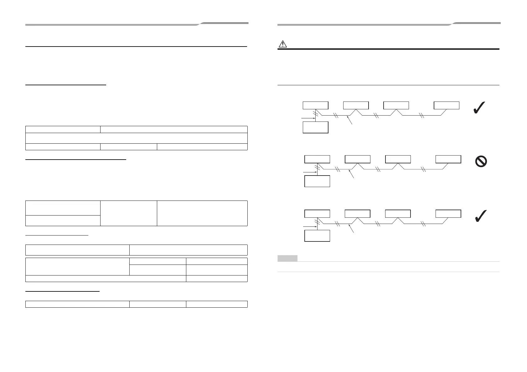
HWM : Hot Water Module
It is not possible to connect any Hot Water Modules and any indoor units together for group control.
L1
L
L2 Ln
Indoor unit
Remote controller inter-unit wiring
Indoor unit Indoor unit Indoor unit
Remote
controller
(Max. 8 units)
Remote
controller
wiring
Correct
L1 L2 Ln
L
HWM
Indoor unit Indoor unit Indoor unit
Remote
controller
(Max. 8 units)
Incorrect
Remote controller inter-unit wiring
Remote
controller
wiring
Ln
(
*
)
L
L1 L2
HWM HWM HWM HWM
Remote
controller
(Max. 8 units)
Correct
Remote controller inter-unit wiring
Remote
controller
wiring
(*) : In the case of multiple refrigerant systems
41-EN 42-EN
+00EH99897401-3_00Ta.book Page 21 Wednesday, May 11, 2016 3:36 PM
 Loading...