–22–
EN
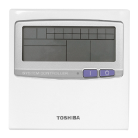
Wiring between indoor (including hot water module) and outdoor
units
• An outdoor unit connected with control wiring between indoor (including hot water module) and outdoor units wire
becomes automatically the header unit.
• Do not turn off the circuit breaker of the hot water module when the circuit breaker of the system (outdoor unit)
is set to the ON position.
• It becomes a cause of a trouble.
▼ Wiring example
U1 U2
U1 U2 U3 U4L1 L2 L3 N U5 U6
LN AB
AB
U1 U2 U3 U4L1 L2 L3 N U5 U6
U1 U2LN AB
AB
U1 U2LN AB
AB
U1 U2LN AB
Outdoor Power supply
380 V - 415 V ~, 50 Hz
Circuit breaker,
Power switch
Remote controller
Indoor unit
Outdoor Power supply
380 V - 415 V ~, 50 Hz
Remote controller Remote controller
Indoor unit Hot water module
Circuit breaker Circuit breaker
Header outdoor
unit
Follower outdoor
unit
Control wiring between outdoor units
Control wiring between indoor and outdoor units
Control wiring between indoor units
Indoor power supply
220 V - 240 V ~, 50 Hz
Earth Earth Earth Earth
Group control
Pull boxPull boxPull box
Earth
terminal
Earth
terminal
Hot water module
In the case of connecting
two hot water modules.
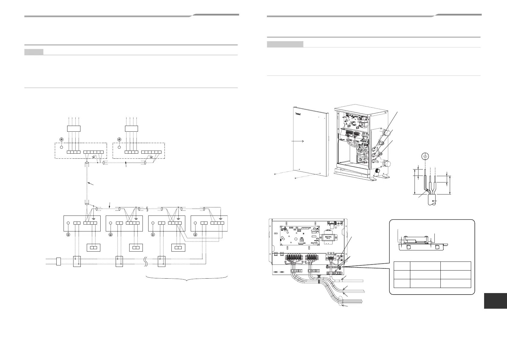
Wire connection
• Connect the wires matching the terminal numbers. Incorrect connection causes a trouble.
• Pass the wires through the bushing of wire connection holes of the hot water module.
• Keep a margin (Approx. 100 mm) on a wire to hang down the electrical control box at servicing or other purpose.
• The low-voltage circuit is provided for the remote controller. (Do not connect the high-voltage circuit)
• Remove the front panel of the hot water module by taking off the mounting screws (2 positions).
• Tighten the screws of the terminal block, and fix the wires with cord clamp attached to the electrical control box.
(Do not apply tension to the connecting section of the terminal block.)
• Mount the front panel of the hot water module without pinching wires.
Front
panel
Power supply wiring port
Control wiring port
External signal wiring port
Earth wire
Power supply wire
(Unit: mm)
COMS1S2S3S4S5 U1U2 A B
R
(L)
S
(N)
Side D (Space: 8.5 mm)
Side C (Space: 4 mm)
* Cable clamp can be attached on left side.
Wire
type
Specification
Cable clamping
position
Cabtyre
cable
3-core stranded
wire 2.5 mm²
Side D
Cabtyre
cable
4-core stranded
wire 1.5 mm²
Side C
Earth Screw
Cord clamp
(For power supply
wire)
Power supply wire
Remote controller wire
Control wire
Output signal function wire
43-EN 44-EN
+00EH99897401-3_00Ta.book Page 22 Wednesday, May 11, 2016 3:36 PM
 Loading...