–23–
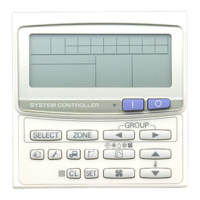
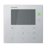
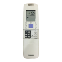
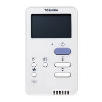
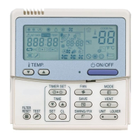
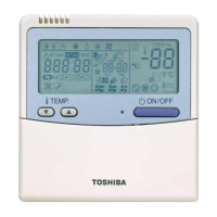
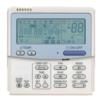
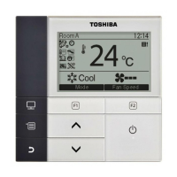
Remote controller wiring
• Strip off approx. 9 mm the wire to be connected.
▼ Wiring diagram
Output signal function wiring
Connect the following output signals from the hot water module.
Auxiliary relays (locally procured) must be connected to output signal function wirings to allow connection to the
hot water module output signal functions. The maximum current output signal, from each of the output signal
function wirings, is 16 mA. Please ensure the rated current of the relay coil is less than 16 mA to avoid damage to
the hot water module P.C. board.
Terminal
block No.
Function Comments
COM DC12V (COM) Common for connector S2 ~ S5
S1 Defrosting output (COM-S1)
DC12V
Relay coil is less than 16mA.
S2 Line heater output (COM-S2)
DC12V
Relay coil is less than 16mA.
S3 - -
S4 Heating thermostat ON output (COM-S4)
DC12V
Relay coil is less than 16mA.
S5 Pump output (COM-S5)
DC12V
Relay coil is less than 16mA.
Terminal block
Remote controller unit
Terminal block for
remote controller wiring
of hot water module
Remote controller wire
(Locally procured)
COM
S1
S2
S3
S4
S5
External
actuator
Output function wire
Hot water module
output signal
function terminal
block (CN60)
Locally procured
Relay
▼ Output function wire
Output signal functions are separated from primary basic insulation.
• To prevent noise trouble, use 2-core shield wire.
• Determine the wire length between the hot water module output signal function terminal block and the relay up
to 2 m.
• Locally procure and install protective devices such as the heater and pump.
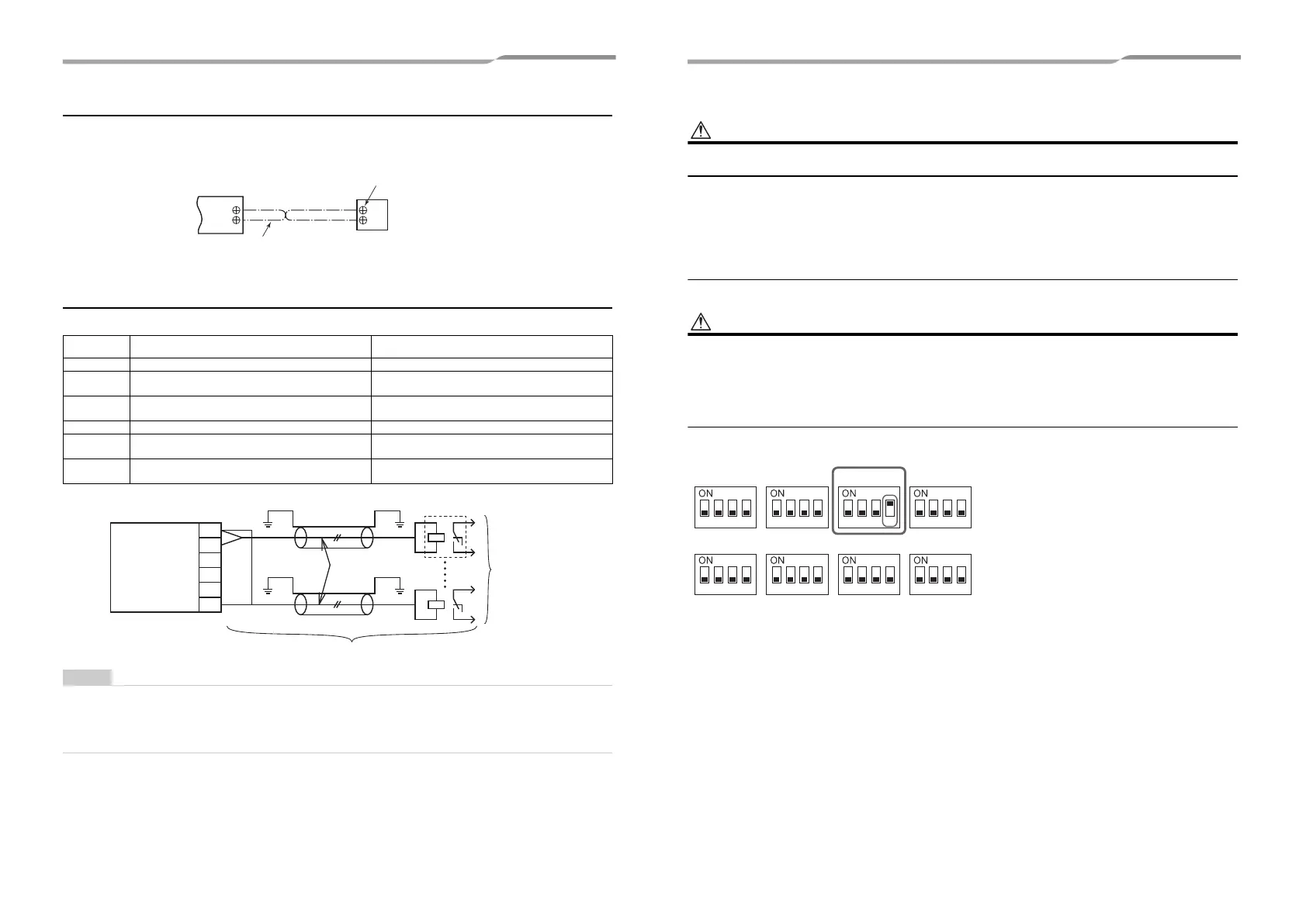
Address setup
Set up the addresses as per the Installation Manual supplied with the outdoor unit.
Set the DIP switch 4 of SW09 on the P.C. board of the header outdoor
unit "ON". (Factory default is "OFF")
VRF system will be stopped to avoid water freezing when the power
supply is disconnected.
Interface P.C. board on the header outdoor unit
SW06 SW07 SW09 SW10
SW11 SW12 SW13 SW14
1234 1234 1234 1234
1234 1234 1234 1234
45-EN 46-EN
+00EH99897401-3_00Ta.book Page 23 Wednesday, May 11, 2016 3:36 PM
 Loading...