1. System configuration
2
I/O system configuration
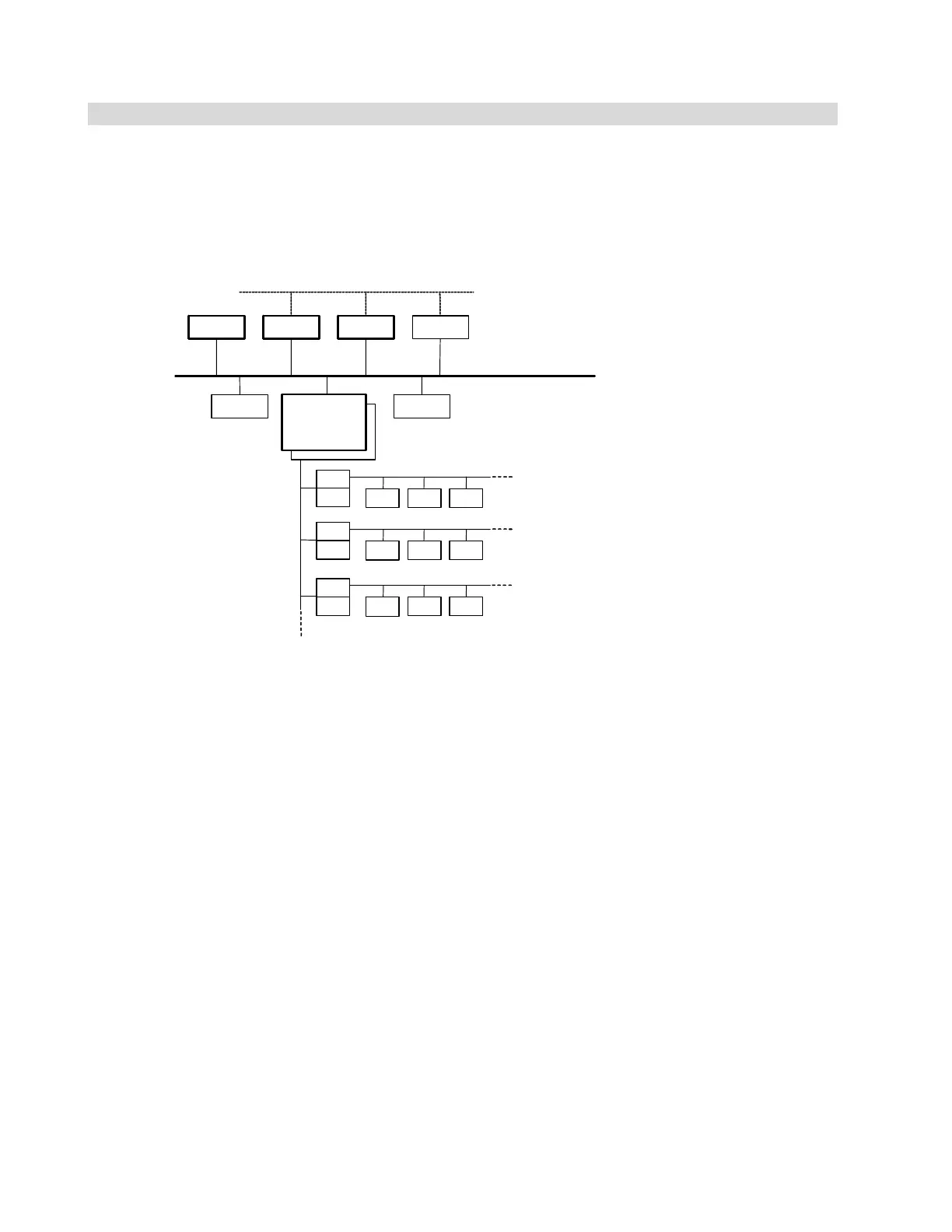
The I/O system is connected to the main control system via the serial bus as shown in Fig. 1.1.
The I/O system consists of the I/O base unit, I/O base card, and I/O module, and is connected to
the terminal block unit of the existing DPCS, as shown in Fig. 1.2.
PLCS-DSPCS-DS
COMP
SVR OIS Tool
SBIF
SVR: Server
OIS: Operator station
(Monitoring operation screen)
COMP: Computer
PCS-DS: CIEMAC controller
PLCS-DC: PLC server
Host information system trunk line LAN
Monitoring control LAN Ethernet
DPCS
emulator
SBIF
LP LP LP
SBIF
SBIF
LP LP LP
SBIF
SBIF
AI TC RTD
I/O component
Loop system component
Loop system component
Main control system
Serial bus
Fig. 1.1 DPCS emulator system configuration
 Loading...


