2. System component
35
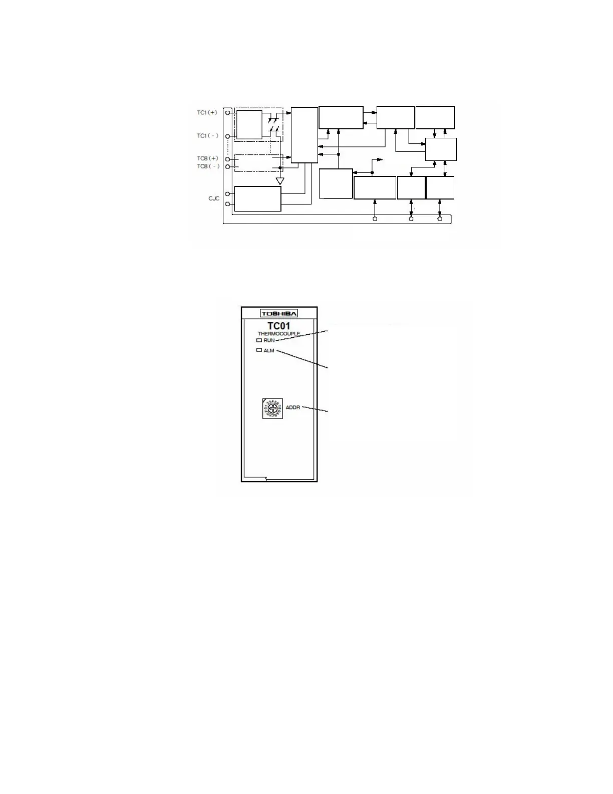
Fig. 2.28 STC012 module internal circuit
Fig. 2.29 STC012 module front part
RUN indicator: Illuminates when normal
Alarm indicator: Blinks upon an error
Module address setting switch:
Set the module number 1 to E (1 to 14).
Bus A Bus B
RS-485
transceiver
Module connector
8CH
analog
multi-
plexer
circuit
V/F converter
circuit
Signal
insulating
circuit
State
display/switch
Insulation
DC/DC
converter
Constant voltage
power circuit
RS-485
transceiver
Internal power
supply
System power supply
(DC24V)
Redundancy I/O bus
Internal CPU
circuit
Input
protection
circuit
Cold junction
compensation
circuit
 Loading...


