19
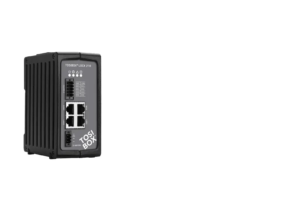
LOCK 210, LOCK 250 AND LOCK 500 INSTALLATION
ON THE TABLE
The Node
designed to provide cooling air passing through the device.
Allow enough free space, minimum of 25mm around the
Node
Make sure there is no risk of the device falling aside as this
make the Lock fall aside and routed as far away from the
pattern, i.e. in such a way that they form 90 degrees angle
To achieve the maximum radio performance, follow the
antenna pattern shown in the picture on the next page.
Avoid installing the Node
Node. Also avoid installing the Node close to any sensitive
Node. In case of unwanted
Node in a place
 Loading...