5
2. C
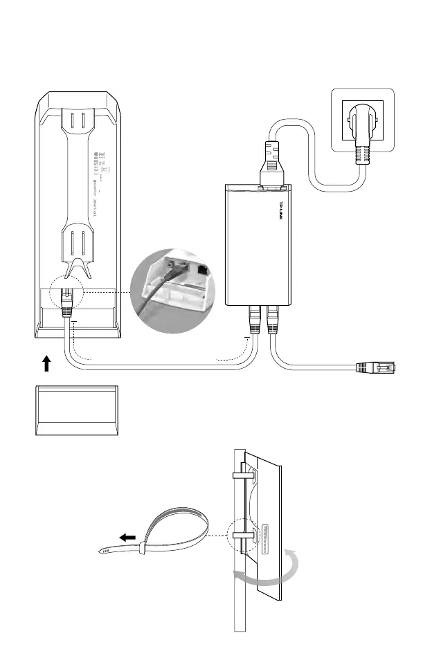
onnection and Installation
A
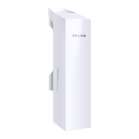
t the selected site,
approximately align the
CPE to the direction that
you have oriented.
You should prepare an adequate
Ethernet cable to connect the CPE
and the passive PoE adapter.
Shielded CAT5e (or above) cable
with ground wire is recommended
(refer to the next section).
P
lease connect and install the device as shown in the gure below.
Connect to a computer,
router or switch.
(Depending on your
intended usage and/or
network topology.)
Ethernet cable length up to 60m
Slide to replace the cover
of the CPE when all
connections are nished.
This
device complies with part 15 of the FCC Rules. Operation is
subject to the following two conditions: (1) This device may not cause
harmful interference, and (2) this device must accept any interference
received, including interference that may cause undesired operation.
FCC ID:TE7CPE510
MADE IN CHINA
IC:8853A-CPE510
Default Settings:
IP: 192.168.0.254 Username: admin Password: admin
Model: CPE510
Power: 24V 1A
5
GHz 300Mbps 13dBi Outdoor CPE
5734
POE
LAN0
LAN
 Loading...