7
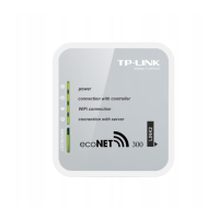
Connection with ecoMAX850P1, D1: 1 – COM
socket (place of plugging a RJ11 interface plug), 2
– a socket with connected plug of the control
panel, 3 –regulator housing cover (possible place
where a control panel can be assembled).
Modules of ecoMAX850P2 controllers are
equipped with just one COM transmission
socket in RJ11 standard which a control
panel (located inside or outside the controller
housing) is connected to. Using one RJ11
socket in the module requires connecting an
additional divider (telephone RJ11 tee
separator) and additional cable.
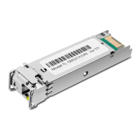
Standard divider, RJ11 telephone divider: 1-
connection of RJ11 ecoLINK2 interface plug, 2-
connection of the control panel plug, 3-
connection of an additional cable with two RJ11
terminals.
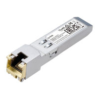
Standard RJ11 telephone cable with an option of
connecting wires and a method of connecting into
the divider.
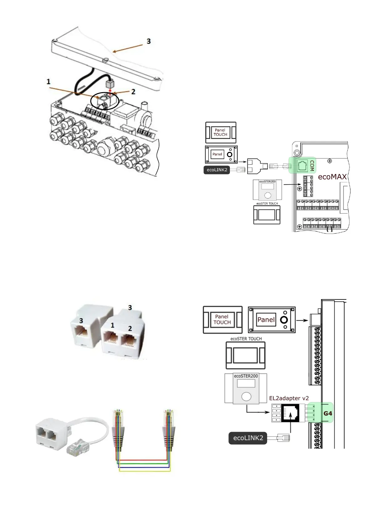
Below show location of the regulator COM
transmission socket, where: interface
ecoLINK2,on diagram includes: COM
transmission socket (connection point
between cable and divider), divider, control
panel, additional ecoSTER TOUCH control
panel (in ecoMAX850I version) and
ecoSTER200, additional cable to a divider.
6.3 Connection with ecoMAX860
series
In case of ecoMAX860P1, P2, P3 series, a
El2adapter v2 must be used in order to
connect ecoLINK2 interface.
P1 version:
P2 version: