04
Gigabit Smart Switch
Introduction
LED Status Indication
PoE Max
On The remaining PoE power≤
7W
Flashing
The remaining PoE power keeps ≤
7W after this LED is
on for 2 minutes
Off The remaining PoE power≥
7W
10/100/
1000Mbps
Green
On The port is supplying power normally
Flashing
The supply power exceeds the correponding port's
maximum power
Yellow
On Overload or short circuit is detected
Flashing Power-on self-test has failed
Off No PoE power supply is provided on the port
LED Mode Switch Button
Press this button to switch the LED status indication between Speed and PoE.
Reset
Press this button for five seconds or above to reset the software setting back to
factory default settings.
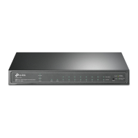
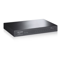
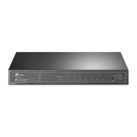
10/100/1000Mbps RJ45 Port
Designed to connect to the device with a bandwidth of 10Mbps, 100Mbps or
1000Mbps. Each has a corresponding 1000Mbps LED.
SFP Port
Designed to install the SFP module. TL-SG2424P switch features 4 SFP transceiver
slots that are shared with the associated RJ45 ports. The associated two ports are
referred as a
“
Combo
”
port, which means they cannot be used simultaneously,
otherwise only SFP port works.
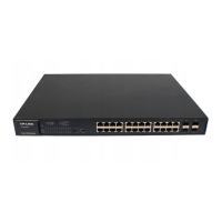
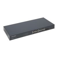
The front panel of TL-SG2452 is shown as the following figure.
SFP Port
Reset
10/100/1000Mbps RJ45 Port
49
30 32 34 36 38
40
42
44
46 48
2
4
6810
12 14
16 18 20
22 24
26 28
29
31 33
35 37 39
41
43 45
47
25
271
3
5
79
11
13
15
17
19
21
23
50 51 52
1000Mbps
10/100Mbps
1000Base-X
LEDs
Figure 1-4 Front Panel of TL-SG2452
LEDs
LED Status Indication
PWR
On The switch is powered on
Off The switch is powered off or power supply is abnormal
Flashing Power supply is abnormal
SYS
Flashing The switch works properly
On/Off The switch works improperly
 Loading...