Printed in the Federal Republic of Germany TR-Electronic GmbH 2019, All Rights Reserved
06/12/2019 TR - ECE - BA - GB - 0142 - 01 Page 23 of 29
Components:
1: Measuring system with blind-hole shaft or hollow shaft
2: Alignment pin, provided by customer: Diameter 4 mm with m6 fit
Length = distance between reference planes X and Y + deviation C +
an immersion depth of 4 ... 5.5 mm
3: Groove insert 4K7, 6 mm deep
4: Groove, according to the article number in the referenced drawing
5: Parallel key: DIN 6885-A 3x3x10
6: Drive shaft with g7 fit, provided by customer
7: Clamping ring with screw, tightening torque = 3 Nm, secured against loosening
8: Measuring system – shaft with H7 fit, according to article number in referenced drawing
Dimensions:
A: Immersion depth for model with blind-hole shaft, according to article number in referenced drawing
B: Immersion depth for model with hollow shaft, according to article number in referenced drawing
C: Clamping ring width, according to the article number in the referenced drawing
Reference planes, minimum clearance:
X: customer-provided device plane
Y: front surface of clamping ring
Minimum clearance: > 1.5 mm
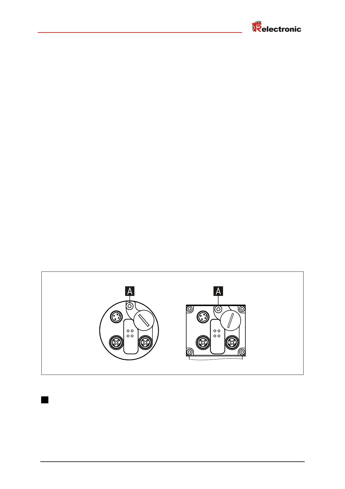
5.3 Potential equalization – connection
Figure 3: Grounding point
A : M4 thread for equipotential bonding





 To Next Page