EasyManua.ls Logo

TR-Electronic CDV582 User Manual

TR-Electronic CDV582
91 pages
To Next Page IconTo Next Page
Page #1 background imageLoading...
Page #1 background image
TR-ECE-BA-GB-0163 v03 10/07/2020
User Manual
Interface
_Safety instructions
_Installation
_Commissioning
_Parameterization
_Error causes and remedies
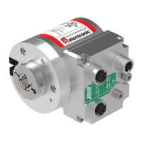
Absolute Encoder CD_582
EtherNet/IP
/ CIP Safety
OPTION: Optional interface
Original manual
DIN EN 61508 / DIN EN 62061: SIL2 / SIL CL 2, SIL3 / SIL CL 3
DIN EN ISO 13849:
PL d / PL e
CDV582
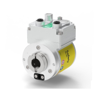
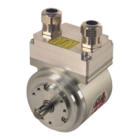
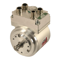
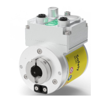
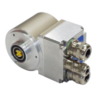
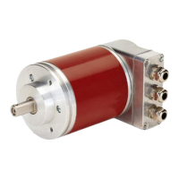
Pictures are similar
Notice: This PDF is not subject to an updating service
Get the most recent version:
https://www.tr-electronic.de/f/TR-ECE-BA-GB-0163

Table of Contents

Other manuals for TR-Electronic CDV582

Questions and Answers:

TR-Electronic CDV582 Specifications

General IconGeneral
BrandTR-Electronic
ModelCDV582
CategoryMedia Converter
LanguageEnglish

Summary

General Information

Scope of Application

Defines the application range and article numbers for the encoder.

Main Features of the Encoder

Highlights key features like EtherNet/IP, CIP Safety, and dual-channel scanning.

Principle of Safety Function

Explains how system safety is established through internal comparisons and diagnostics.

Safety Instructions

Definition of Symbols and Notes

Explains warning, caution, and notice symbols used in the manual.

Safety-Related Requirements for CIP Safety™ Devices

Details essential user responsibilities and checks for safe operation with CIP Safety™.

Safety Functions of Fail-Safe Processing Unit

Describes how the system ensures safety by handling errors and passivated data.

Installation and Preparation for Commissioning

Basic Installation Rules

Covers fundamental safety and installation principles for devices and wiring.

EtherNet/IP Transmission Technology and Cable Specification

Specifies network topology, cable types, and switch requirements.

Connection Notes

Provides essential information regarding connectors, moisture protection, and supply voltage.

Additional Interfaces Hardware Description

Describes hardware options like Incremental, SIN/COS, and SSI interfaces.

Defining the Target Unique Network Identifier (TUNID)

Explains how to uniquely identify the measuring system in the safety network.

Commissioning Procedures

Device Identification

Details attributes used for device verification and electronic keying.

Bus Status Display

Explains the meaning of diagnostic LEDs for system status monitoring.

Downloading Safety-Related Configuration

Guides through the process of downloading and verifying configurations using the SNCT tool.

Resetting Safety-Related Device Parameters

Configuration Data Structure

Instance 103: Grey Config Channel 1

Details configuration data for Instance 103, including direction toggle.

Instance 104: Grey Config Channel

Describes TR Grey attributes for non-safety-related configuration assembly.

Instance 123: Safety Config

Outlines safety-related attributes for configuration assembly.

Cyclic Process Data Structure (IO Assembly)

Instance 1: Grey Default Input

Details the non-safety-related default input for position value.

Instance 101: TR Grey Input

Describes non-safety-related data output for TR Grey.

Instance 121: Safety Input

Details safety-related data output for TR Safety.

Connection Types and Points

Exclusive Owner Connection Type

Describes an independent connection controlling target device output states.

Input Only Connection Type

Explains connections receiving inputs from the target device.

Non-Safety-Related Connections

Lists and describes connection points for non-safety-related data flow.

Safety-Related Connections

Lists and describes connection points for safety-related data flow.

Parameter Description

Object 0x23 (Instance 1): Position Sensor Parameters

Details attributes for the Position Sensor object, including non-safety and safety parameters.

TR Grey Scaling Parameter

Defines TR Grey scaling parameters like Measuring Range, Numerator, Denominator.

TR Safety Scaling Parameter

Defines TR Safety scaling parameters for measuring range and revolutions.

TR Safety SIL / PL Level

Specifies the expected Safety Integrity Level (SIL) for the safety-related device.

TR Safety Preset Adjustment Function

Preset Adjustment Procedure

Outlines the step-by-step process for executing the preset adjustment function.

Calculating Delay for Moving Axis

Explains how to calculate the delay when adjusting a moving axis.

Obtain IP Parameters via Flash or DHCP

Object 0xF5, Instance 1 Configuration

Covers configuration of the TCP/IP network interface via Object 0xF5.

Example: Obtaining IP Parameters via DHCP Server

Provides a practical guide for setting IP parameters using a DHCP server.

Error Causes and Remedies

Optical Displays (LEDs)

Explains diagnostic meanings of module and network status LEDs.

Miscellaneous Faults

Lists common faults like position jumps and their causes/solutions.

Checklist for Commissioning and Verification

Related product manuals