Installation / Preparation for Commissioning
TR-Electronic GmbH 2020, All Rights Reserved Printed in the Federal Republic of Germany
Page 30 of 91 TR-ECE-BA-GB-0163 v03 10/07/2020
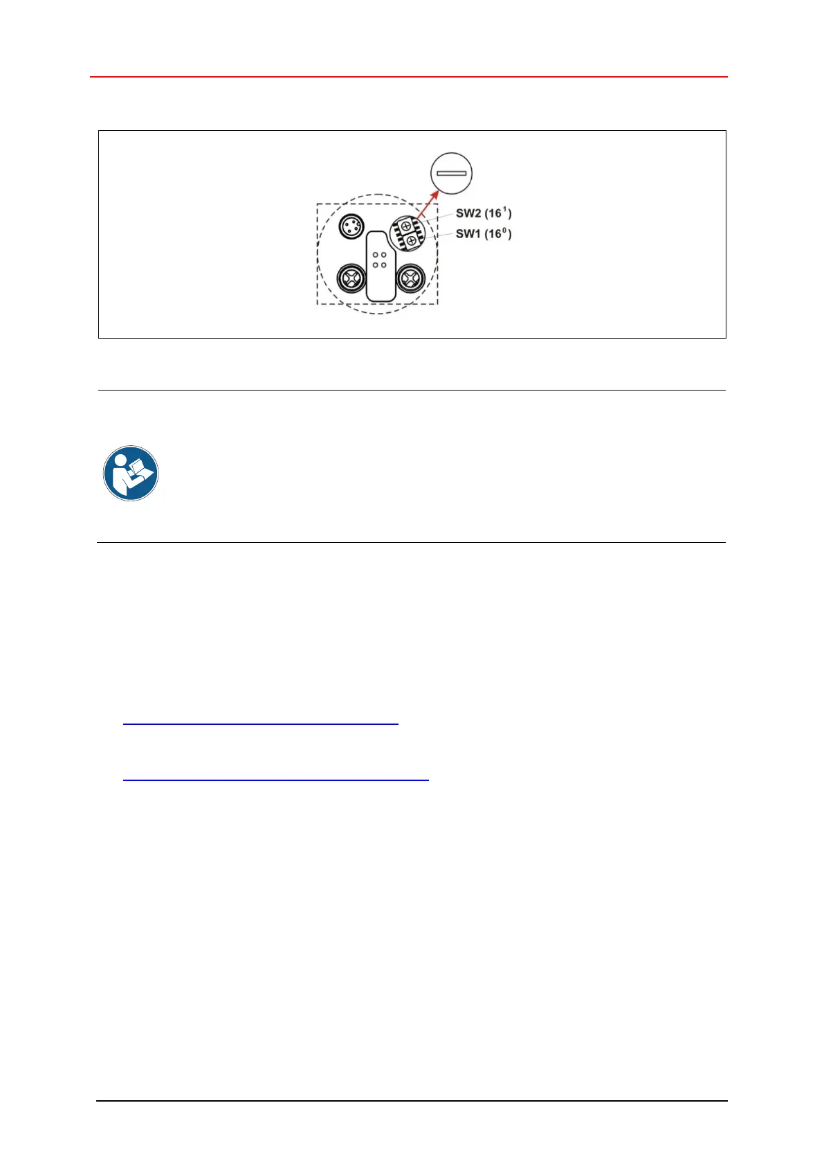
Node IDs 1 to 254 may be assigned to the measuring system.
Figure 8: EtherNet/IP™ node ID, switch assignment
The following provisions apply when the HEX rotary switches are activated:
● IP address = 192.168.1.<preset node ID>
● Subnet mask = 255.255.255.0
● Default Gateway = 192.168.1.254
For obtaining the configuration from a FLASH or via a DHCP server,
please refer to “Attribute 5, Interface Configuration” as from Page 78.
3.5.2 Programming the Safety Network Number (SNN)
TR-Electronic provides the WINDOWS
®
program TR SNCT Device Applet to configure the
measuring system according to the “SNCT-to-Originator and SNCT-to-Target” scheme and to
configure firmware updates and diagnostic options:
Download program description:
● www.tr-electronic.de/f/TR-ECE-TI-DGB-0364
Download TR SNCT Device Applet:
● www.tr-electronic.de/f/zip/TR-ECE-SW-MUL-0016
See the program description for program installation, system requirements, device connection and
possible use cases.
Ensure that no controller is connected to the measuring system and that there is no EtherNet/IP™
communication during programming.
The following procedure assumes that the corresponding network interface and IP address of the
measuring system have been set in the TR SNCT Device Applet and that there is communication.
SNN input format: „****_****_****“ (6 Byte); ´*´ = 4 Bit, HEX coded (0-9, A-F)
To improve readability, the separator “_” is required after every 2 bytes.
CIP data type for DATE_AND_TIME: [DATE_WORD]_[TIME_HI_WORD]_[TIME_LO_WORD]