©1999 Trace Engineering
2.0 INSTALLATION
7
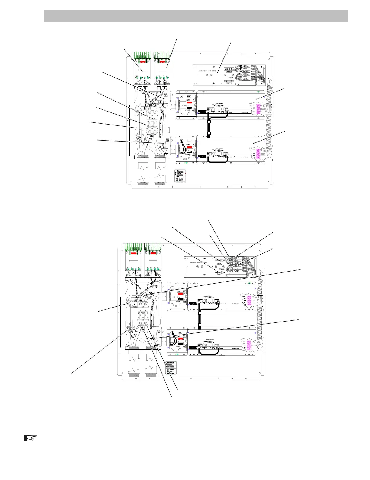
Figure 5
Component Locations (DR Model)
Figure 6
Wire Connection Locations (DR Model)
PV Array #1 Controller (optional)
*PV Array #2 Controller (optional)
AC Disconnect/Bypass Box
Inverter #1
*Inverter #2
Solar (PV) Array #1
Disconnect
*Solar (PV) Array #2
Disconnect
*Battery (positive)
Disconnect #2
Battery (positive)
Disconnect #1
DC Negative
Ground Bond
NOTE: Items marked with an astrict (*) are only applicable to dual inverter/controller models.
120 V ac
Output 1
AC INPUT from LINE 1
(black)
*AC INPUT from LINE 2
(red)
All NEUTRAL wires (white)
AC GROUND wires
*Battery POSITIVE Terminal
Battery POSITIVE Terminal
PV Array
Chassis GROUND
PV Array NEGATIVE
DC Earth GROUND
Battery
NEGATIVE
PV Array 1
POSITIVE
*PV Array 2
POSITIVE
*120 V ac
Output 2