B
ENGINE
Read all of SAFETY and this section before attempting any procedure. Pay particular attention to Notices, Cautions, Warnings and Dangers.
79
Repair and Service Manual
699322
2. Condition of the valve seating.
3. Valve clearance.
4. Piston/cylinder wear, piston seizure.
5. Piston ring, piston ring groove.
Rocker Cover Removal
Tool List Qty.
Ratchet........................................................................ 1
Extension 6" ................................................................ 1
Socket, 10 mm ............................................................ 1
1. Remove the four bolts (5) securing the rocker cover.
2. Remove the rocker cover (2) and the gasket.
Fig. 17 Rocker Cover
Valve Clearance Inspection
Tool List Qty.
Allen Bit, 3 mm ............................................................ 1
Ratchet........................................................................ 1
Extension 6" ................................................................ 1
Feeler Gauge .............................................................. 1
Wrench, 14 mm ........................................................... 1
Torque Wrench, in. lbs................................................. 1
NOTICE: Valve clearance must be checked when the
engine is cold (at room temperature).
With the rocker cover removed, Place the piston at TDC
of the compression stroke turning the crankshaft in its
rotational direction.
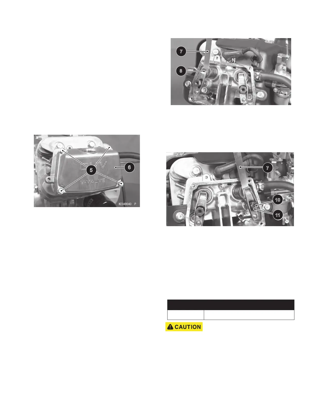
Then check the valve clearance with a feeler gauge (7),
measure the valve clearance between the rocker arm (8)
and the valve stem end.
Valve Clearance (when cold): Inlet, Exhaust 0.10 - 0.15
mm (0.004 - 0.006 in.)
Fig. 18 Measure Valve Clearance
If the valve clearance is incorrect, adjust it.
Valve Clearance Adjustment
Turn the crankshaft to the proper direction until the piston
is at TDC of the compression stroke.
Fig. 19 Valve Clearance Adjustment
Valve Clearance (when cold): Inlet, Exhaust 0.10 - 0.15
mm (0.004 - 0.006 in.)
Loosen the lock screw (10) using the 3 mm Allen bit and
the adjusting nut (11). Insert the feeler gauge (7) between
the rocker arm and the valve stem end and move the
adjusting nut (11) until the feeler gauge begins to bind
between the rocker arm and the valve stem end.
Hold the adjusting nut (11) in place using a wrench and
tighten the lock screw (10) to the specified torque.
Do NOT over-tighten.
Remeasure any clearance that was
adjusted. Readjust if necessary.
Replace the Rocker Cover (6), gasket and the four bolts
(5). Tighten the bolts to secure the cover in place.
5
6
ITEM TORQUE SPECIFICATION
10 61 in. lbs (6.9 Nm)
7
8
7
10
11