B
SUSPENSION AND SFRONT SUSPENSION AND STEERING
Read all of SAFETY and this section before attempting any procedure. Pay particular attention to Notices, Cautions, Warnings and Dangers.
57
Repair and Service Manual
699322
tightening as required in order to insert a new cotter
pin. Maximum torque is 50 ft. lbs. (70 Nm).
9. Install front wheel(s) per WHEELS AND TIRES sec-
tion and lower vehicle per SAFETY section.
10. A worn tie rod is likely to have caused incorrect
wheel alignment. Check front wheel alignment and
adjust if necessary. See the Wheel Alignment on
page 49.
11. Jam nut should be tightened to 36 - 40 ft. lbs. (49 -
54 Nm) torque.
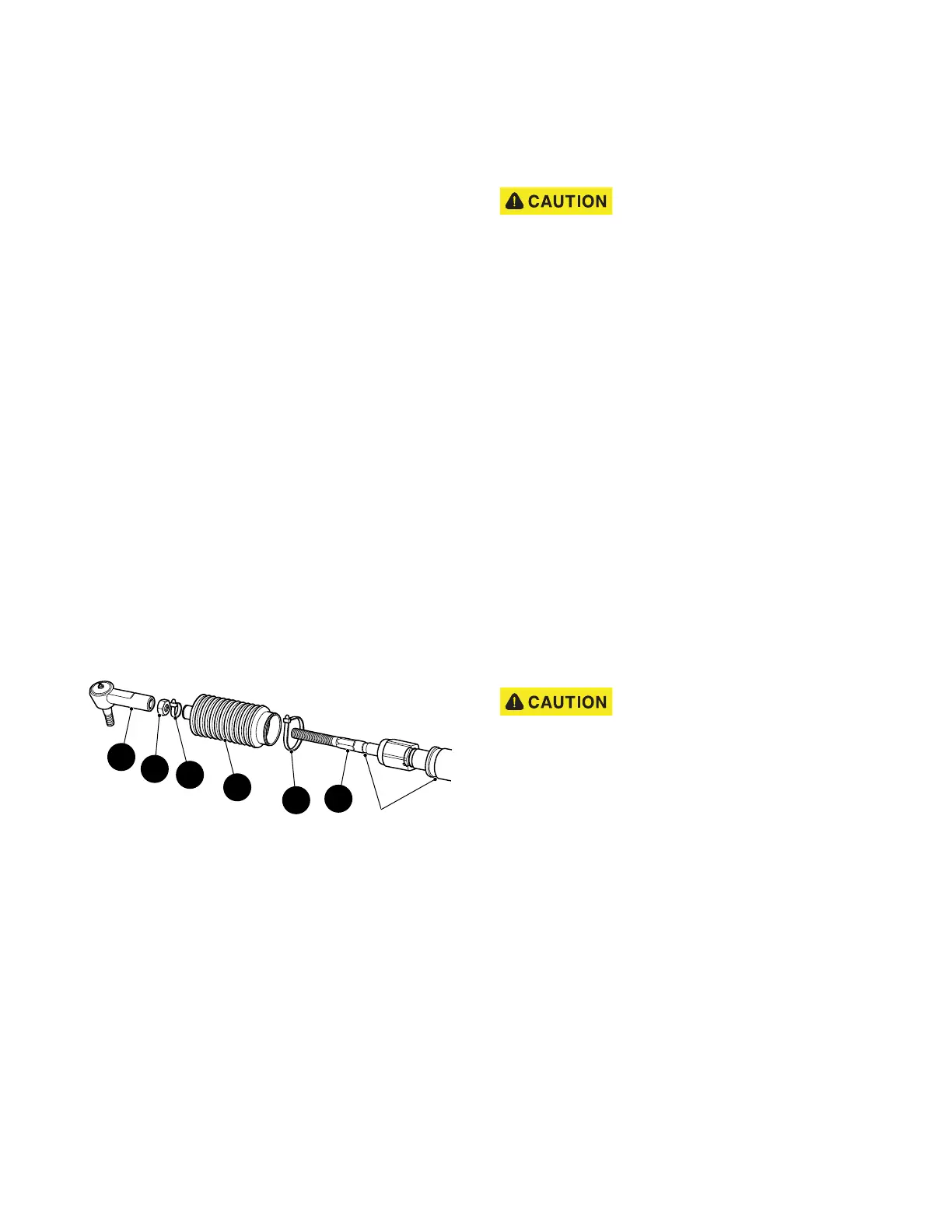
Bellows Replacement
Tool List Qty.
Needle Nose Pliers...................................................... 1
Wrench, 11/16" ............................................................ 1
Ball Joint Separator..................................................... 1
Plastic Faced Hammer ................................................ 1
Tape Measure.............................................................. 1
Wrench, 3/4"................................................................ 1
Wire Cutters ................................................................ 1
Wire Tie, 8" long .......................................................... 1
Torque Wrench, ft. lbs. ................................................ 1
Socket, 11/16” ............................................................. 1
1. To replace bellows (1) (Ref. Figure 14), first loosen
passenger side front wheel and lift and support front
of vehicle per SAFETY section.
Figure 14 Bellows Replacement
2. Remove passenger side front wheel and turn steer-
ing wheel fully to the left.
3. Remove rack ball joint (2) and jam nut (3) from rack
extension(4). See the Rack Ball Joint Replacement
on page 55
4. Cut wire ties (5,6) and slide bellows off rack exten-
sion. Install new bellows aligning small end over
groove in rack extension and secure with new wire
tie (5). Leave large end loose until rack extension-to-
rack and pinion unit clearance is checked or
adjusted.
5. Install jam nut (3) and rack ball joint (2) on rack
extension (4) and reattach to spindle arm. See the
Rack Ball Joint Replacement on page 55
After replacing or servicing steering
components, always verify that an
1/8" gap exists between large hex of
rack extension and rack and pinion unit when steer-
ing is turned fully to the right forcing passenger
spindle arm against front axle.
6. Check for proper rack extension-to-rack and pinion
unit clearance before tightening jam nut (3) to 35 - 45
ft. lbs. (47 - 61 Nm) torque. See the Checking/Adjust-
ing Rack Extension-to-Rack and Pinion Unit Clear-
ance on page 60.
7. Install passenger side front wheel per WHEELS AND
TIRES section and lower vehicle per SAFETY sec-
tion.
8. Check front wheel alignment and adjust if necessary.
See the Wheel Alignment on page 49.
Pinion Seal Replacement
Tool List Qty.
Vice..............................................................................1
Straight Blade Screwdriver, small ................................1
Ball Peen Hammer.......................................................1
Sandpaper, 600 grit ..................................................AR
Shop Towel ...............................................................AR
Wheel Bearing Grease .............................................AR
Socket, 1 1/2”...............................................................1
Secure rack and pinion unit in vice
by the mounting ears only. The rack
and pinion unit is made of alumi-
num and can be damaged if held otherwise.
1. To access the pinion seal, remove rack and pinion
unit from vehicle. See the Rack and Pinion Unit
Replacement on page 60 Anchor in vice by clamping
on the mounting ears of the rack and pinion unit.
2. Slide a small straight blade screwdriver between lip
of seal and pinion and pry top portion of seal up to
remove (Ref. Figure 15).
Grooves
4
2
5
1
3
6