B
SUSPENSION AND SFRONT SUSPENSION AND STEERING
Read all of SAFETY and this section before attempting any procedure. Pay particular attention to Notices, Cautions, Warnings and Dangers.
55
Repair and Service Manual
699322
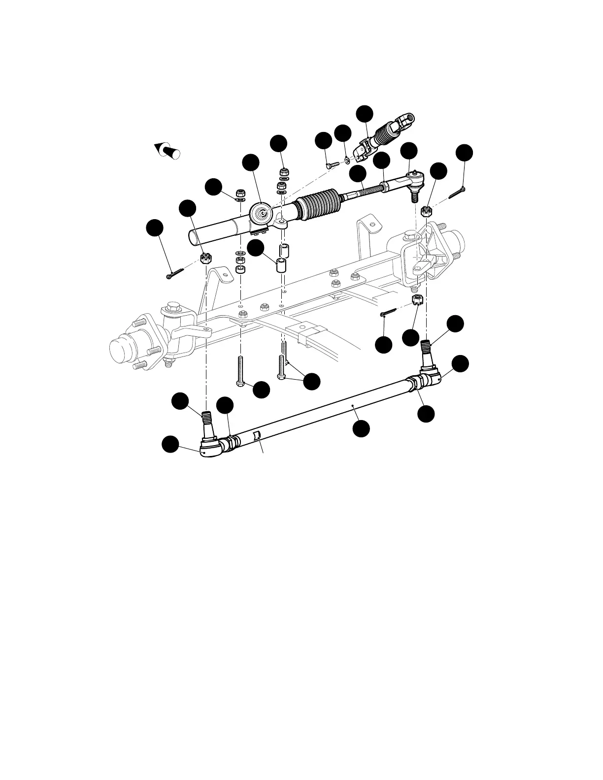
Fig. 11 Steering Components
Rack Ball Joint Replacement
Tool List Qty.
Needle Nose Pliers...................................................... 1
Wrench, 11/16" ............................................................ 1
Ball Joint Separator..................................................... 1
Plastic Faced Hammer ................................................ 1
Tape Measure.............................................................. 1
Wrench, 3/4"................................................................ 1
Torque Wrench, ft. lbs. ................................................ 1
Socket, 11/16" ............................................................. 1
1. To remove rack ball joint (1), loosen passenger side
front wheel and lift and support front of vehicle per
SAFETY section (Ref. Fig. 11).
2. Remove passenger side front wheel and turn steer-
ing wheel fully to the left.
3. Remove the cotter pin (2) and loosen the castellated
nut (3) until rack ball joint (1) threads are protected.
Using a ball joint separator as a lever, apply pressure
to ball joint and tap nut with plastic faced hammer to
release ball joint from passenger side spindle arm.
Remove nut from ball joint and ball joint from spindle
arm.
4. To install new rack ball joint close to its correct posi-
tion, measure amount of threads exposed from jam
nut (Ref. Figure 12).
Front of Vehicle
Flat
Section
18
12
19
10
20
17
11
11
16
9
6
6
2
3
7
8
7
10
15
14
13
9
1
4
5