T10 Installation Notes v1.7
Generic T10 Installation Notes v1.7.doc 12.08.2015
Page 11
5.3 Backup Battery
The T10-Lite products can be supplied with a Li-ion Polymer 3.7v 1500mAh backup battery for
operational scenarios where the main power can be removed or the main power is required to be
monitored and alerted against in the event of a disconnection.
This Battery can ONLY be fitted/replaced as part of the production process of the unit and is NOT
a user fit/replacement feature. It MUST be returned to Factory for replacement.
5.4 Mounting the T10-Lite
You may choose to mount the Control Unit somewhere covertly e.g. in the boot, under the
parcel-shelf or under the dashboard. Suitable mechanical fixings such as cable ties can be used
(not supplied).
WARNINGS:
1. Your T10 Platform must be securely mounted in a location where it cannot
interfere with the normal operation of the vehicle. It must NOT be located in a
position where the cables or the Control Unit become a hazard to the driver or
passengers.
2. Under no circumstances may any part of the T10 system be installed inside
the engine compartment area.
3. For correct calibration of the accelerometer functions it is imperative that the
unit is securely mounted such as to maximise the auto calibration procedures
on board the unit. This is best achieved with the unit mounted flat in either the
horizontal or vertical plane.
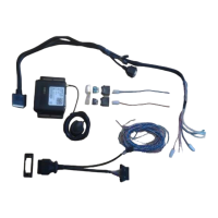
5.5 T10-Lite Wiring and Connections
Important Notes!
1. Unauthorised changes or alterations to the equipment or the installation will invalidate
certification issued by the Approved Accreditation Body and could also affect the vehicle
manufacturer’s warranty.
2. The notes below should be read in conjunction with the T10 Block Diagrams.
3. All wiring should be professionally connected to the vehicle electrics via soldered connections
using automotive grade fuse holders and fuses.
4. All wiring should be safely secured to avoid damage from, or chaffing by, any hot or moving
parts.
5. Position the wiring carefully to avoid the possibility of snagging or impact damage during the
normal use of the vehicle.
6. Before any holes are drilled, check that no parts, wires, pipes or tanks could be damaged at
the exit point of the hole. Suitable grommets must be used where wires are routed through
body panels to prevent chaffing and short circuits to the chassis.
7. Leave the in-line fuses out of their holders until the installation is complete.